Pin description – Rainbow Electronics MAX1706 User Manual
Page 9
MAX1705/MAX1706
1- to 3-Cell, High-Current, Low-Noise,
Step-Up DC-DC Converters with Linear Regulator
_______________________________________________________________________________________
9
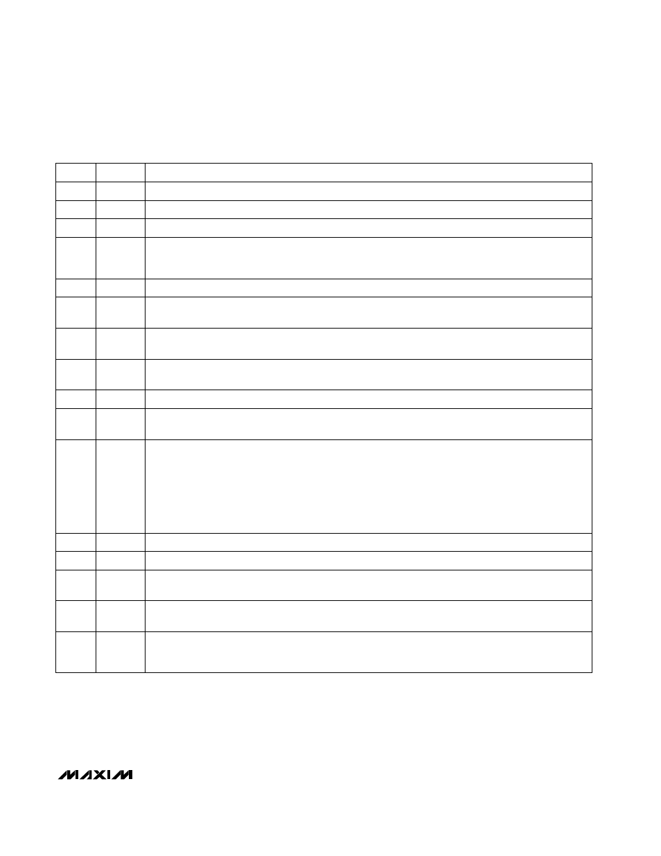
______________________________________________________________Pin Description
Boost DC-DC Converter Power Output. POUT is the source of the P-channel synchronous-rectifier MOSFET
switch. Connect an external Schottky diode from LX to POUT. The output current available from POUT is
reduced by the current drawn from the LDO linear-regulator output.
POUT
16
On Control Input. When ONA = high or ONB = low, the IC turns on. Connect ONA to OUT for normal
operation (Table 2).
ONA
15
Off Control Input. When ONB = high and ONA = low, the IC is off. Connect ONB to GND for normal
operation (Table 2).
ONB
14
Inductor connection to the drains of the P-channel synchronous rectifier and N-channel switch
LX
13
Power Ground for the source of the N-channel power MOSFET switch
PGND
12
Low-Dropout Linear-Regulator Output. LDO sources up to 200mA. Bypass to GND with a 22µF capacitor.
LDO
9
Low-Battery Comparator Output. This open-drain, N-channel output is low when LBP < LBN.
Input hysteresis is 16mV.
LBO
10
Switching-Mode Selection and External-Clock Synchronization Input:
• CLK/SEL = low: low-power, low-quiescent-current PFM mode.
• CLK/SEL = high: low-noise, high-power PWM mode. Switches at a constant frequency (300kHz). Full
output power is available.
• CLK/SEL = driven with an external clock: low-noise, high-power synchronized PWM mode.
Synchronizes to an external clock (from 200kHz to 400kHz).
Turning on the DC-DC converter with CLK/SEL = GND also serves as a soft-start function,
since peak inductor current is reduced.
CLK/SEL
11
Ground
GND
5
Step-Up Converter Feedback Input, used during track mode. IC power and low-dropout linear-regulator
input. Bypass OUT to GND with a 0.1µF ceramic capacitor placed as close to the IC as possible.
OUT
6
Step-Up DC-DC Converter Feedback Input. Connect FB to a resistor voltage divider between POUT and
GND to set the output voltage between 2.5V and 5.5V. FB regulates to 1.233V.
FB
7
Low-Dropout Linear-Regulator Feedback Input. Connect FBLDO to a resistor voltage divider between LDO
to GND to set the output voltage from 1.25V to V
OUT
- 0.3V (5.0V max). FBLDO regulates to 1.250V.
FBLDO
8
Track-Mode Control Input for DC-DC Converter. In track mode, the boost-converter output is sensed at
OUT and set 0.3V above LDO to improve efficiency. Set TRACK to OUT for track mode. Connect TRACK to
GND for normal operation.
TRACK
4
1.250V Reference Output. Bypass REF with a 0.33µF capacitor to GND. REF can source up to 50µA.
REF
3
PIN
Low-Battery Comparator Inverting Input. Common-mode range is 0.5V to 1.5V.
LBN
2
Low-Battery Comparator Noninverting Input. Common-mode range is 0.5V to 1.5V.
LBP
1
FUNCTION
NAME