Detailed description – Rainbow Electronics MAX1706 User Manual
Page 10
MAX1705/MAX1706
1- to 3-Cell, High-Current, Low-Noise,
Step-Up DC-DC Converters with Linear Regulator
10
______________________________________________________________________________________
_______________Detailed Description
The MAX1705/MAX1706 are designed to supply both
power and low-noise circuitry in portable RF and data-
acquisition instruments. They combine a linear regula-
tor, step-up switching regulator, N-channel power
MOSFET, P-channel synchronous rectifier, precision
reference, and low-battery comparator in a single 16-
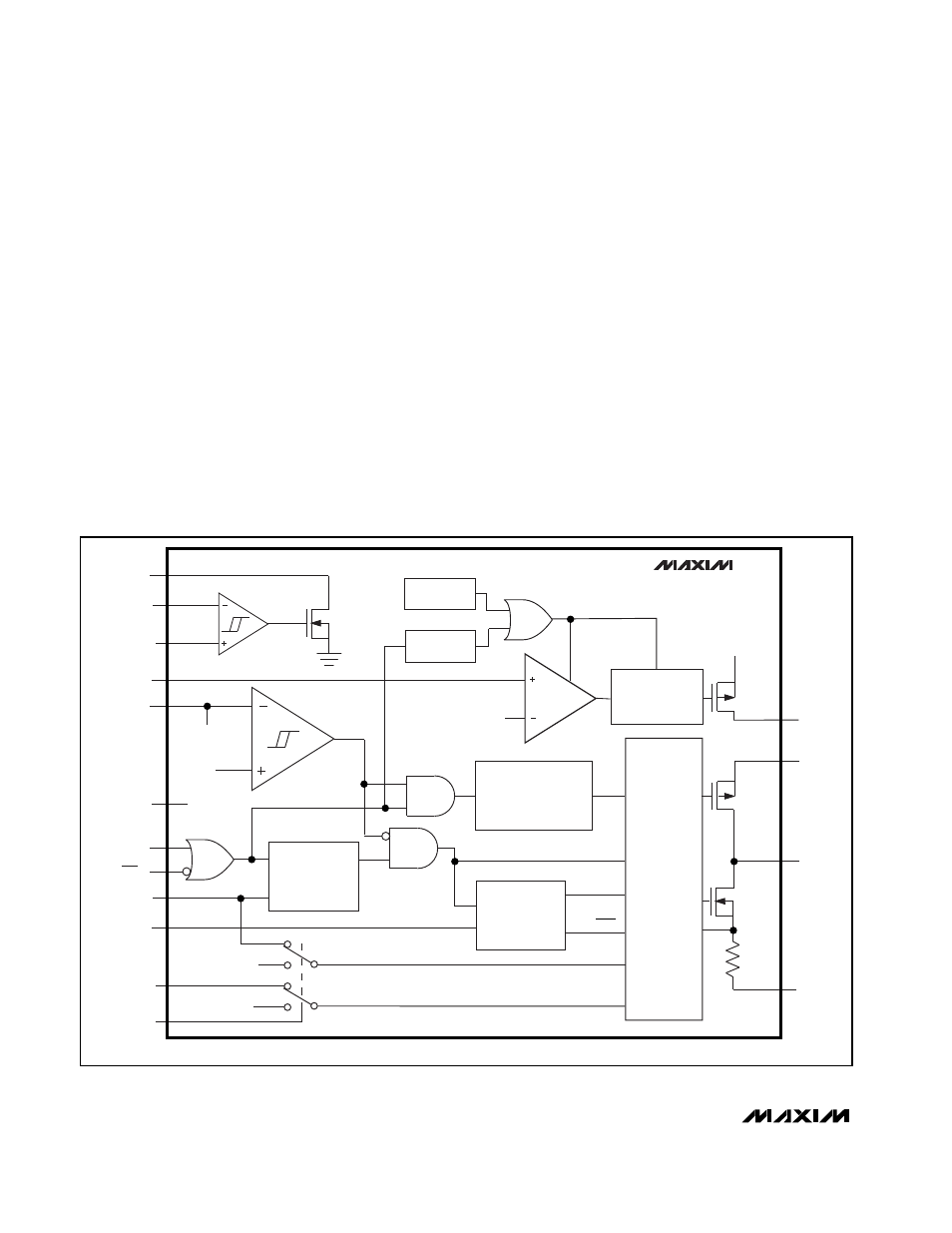
pin QSOP package (Figure 1). The switching DC-DC
converter boosts a 1- or 2-cell input to an adjustable
output between 2.5V and 5.5V. The internal low-dropout
regulator provides linear post-regulation for noise-
sensitive circuitry, as well as outputs from 1.25V to
300mV below the switching-regulator output. The
MAX1705/MAX1706 start from a low, 1.1V input and
remain operational down to 0.7V.
These devices are optimized for use in cellular phones
and other applications requiring low noise during full-
power operation, as well as low quiescent current for
maximum battery life during standby and shutdown.
They feature constant-frequency (300kHz), low-noise
pulse-width-modulation (PWM) operation with 300mA or
730mA output capability from one or two cells, respec-
tively, with 3.3V output. A low-quiescent-current stand-
by pulse-frequency-modulation (PFM) mode offers an
output up to 60mA and 140µA, respectively, and
reduces quiescent power consumption to 500µW. In
shutdown mode, the quiescent current is further
reduced to just 1µA. Figure 2 shows the standard appli-
cation circuit for the MAX1705 configured in high-
power PWM mode.
Additional features include synchronous rectification for
high efficiency and improved battery life, and an
uncommitted comparator for low-battery detection. A
CLK/SEL input allows frequency synchronization to
reduce interference. Dual shutdown controls allow shut-
down using a momentary pushbutton switch and micro-
processor control.
LBP
FBLDO
OUT
2.15V
ONA
ON
ONB
REF
GND
CLK/SEL
FB
LDO
POUT
LX
PGND
LBO
LBN
REF
SHUTDOWN
LOGIC
THERMAL
SENSOR
MAX1705
MAX1706
ERROR
AMP
START-UP
OSCILLATOR
EN
Q
P
P
N
MOSFET DRIVER
WITH CURRENT
LIMITING
EN
300kHz
OSCILLATOR
EN
D
OSC
MODE
PFM/PWM
Q
Q
IFB
PFM/PWM
CONTROLLER
N
RDY
1.250V
REFERENCE
TRACK
IC PWR
IREF
V
OUT
- 300mV
V
LDO
ICS
OUT
Figure 1. Functional Diagram