Table 3. component selection guide – Rainbow Electronics MAX1706 User Manual
Page 15
MAX1705/MAX1706
1- to 3-Cell, High-Current, Low-Noise,
Step-Up DC-DC Converters with Linear Regulator
______________________________________________________________________________________
15
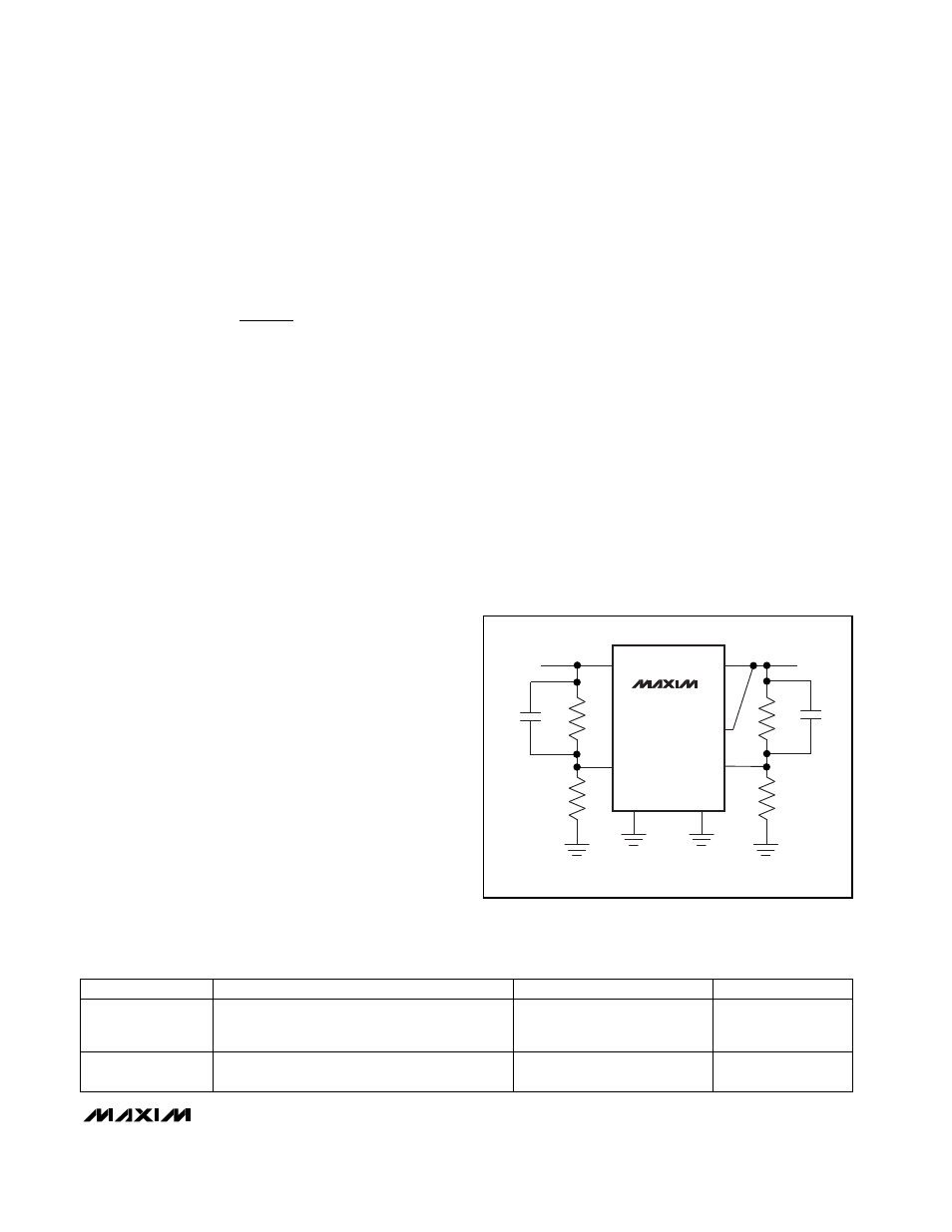
To set the low-dropout linear-regulator output, use a
resistor voltage-divider connected to FBLDO from LDO
to GND. Set the output to a value at least 300mV less
than the step-up converter output using the following
formula:
where V
FBLDO
, the linear-regulator feedback trip point,
is 1.250V. Since the input bias current into FBLDO is
less than 50nA, R4 can be a large value (such as
270k
Ω
or less). Connect the resistor voltage-divider as
close to the IC as possible, within 0.2in. (5mm) of the
FBLDO pin.
Inductor Selection
The MAX1705/MAX1706’s high switching frequency
allows the use of a small surface-mount inductor. Use a
10µH inductor for the MAX1705 and a 22µH inductor
for the MAX1706. Make sure the saturation-current rat-
ing exceeds the N-channel switch current limit of 1.55A
for the MAX1705 and 950mA for the MAX1706. For high
efficiency, chose an inductor with a high-frequency
core material, such as ferrite, to reduce core losses. To
minimize radiated noise, use a torroid, pot core, or
shielded-bobbin inductor. See Table 3 for suggested
parts and Table 4 for a list of inductor suppliers.
Connect the inductor from the battery to the LX pin as
close to the IC as possible.
Attaching the Output Diode
Use a Schottky diode, such as a 1N5817, MBR0520L,
or equivalent. The Schottky diode carries current during
start-up, and in PFM mode after the synchronous rectifi-
er turns off. Thus, the current rating only needs to be
500mA. Attach the diode between the LX and POUT
pins, as close to the IC as possible.
In high-temperature applications, some Schottky
diodes may be unsuitable due to high reverse-leakage
currents. Try substituting a Schottky diode with a higher
reverse voltage rating, or use an ultra-fast silicon rectifi-
er with reverse recover times less than 60ns (such as a
MUR150 or EC11FS1). Do not use ordinary rectifier
diodes, since slow switching speeds and long re-
verse recovery times compromise efficiency and load
regulation.
Choose Input and Output
Filter Capacitors
Choose input and output filter capacitors that service
the input and output peak currents with acceptable
voltage ripple. Choose input capacitors with working
voltage ratings over the maximum input voltage, and
output capacitors with working voltage ratings higher
than the output.
A 100µF, 100m
Ω
, low-ESR tantalum capacitor is recom-
mended at the MAX1706’s step-up output. For the
MAX1705, use two in parallel or a 220µF low-ESR tanta-
lum capacitor. The input filter capacitor (C7) also
reduces peak currents drawn from the input source
and reduces input switching noise. The input voltage
source impedance determines the size required for the
input capacitor. When operating directly from one or
two NiCd cells placed close to the MAX1705/MAX1706,
use a 22µF, low-ESR input filter capacitor. When
operating from a power source placed farther away, or
R
R
V
V
LDO
FBLDO
3
4
=
- 1
OUT
POUT
FB
FBLDO
LDO
GND
PGND
MAX1705
MAX1706
STEP-UP
OUTPUT
LINEAR-
REGULATOR
OUTPUT
R1
R2
R3
R4
C1*
C2*
* OPTIONAL COMPENSATION CAPACITORS
Figure 8. Feedback Connections for the MAX1705/MAX1706
PRODUCTION
INDUCTORS
CAPACITORS
DIODES
Surface Mount
Sumida CDR63B, CD73, CDR73B, CD74B series
Coilcraft DO1608, DO3308, DT3316 series
Matsuo 267 series
Sprague 595D series
AVX TPS series
Motorola MBR0520L
Through Hole
Sumida RCH654 series
Sanyo OS-CON series
Nichicon PL series
Motorola 1N5817
Table 3. Component Selection Guide