Design procedure – Rainbow Electronics MAX1706 User Manual
Page 14
MAX1705/MAX1706
1- to 3-Cell, High-Current, Low-Noise,
Step-Up DC-DC Converters with Linear Regulator
14
______________________________________________________________________________________
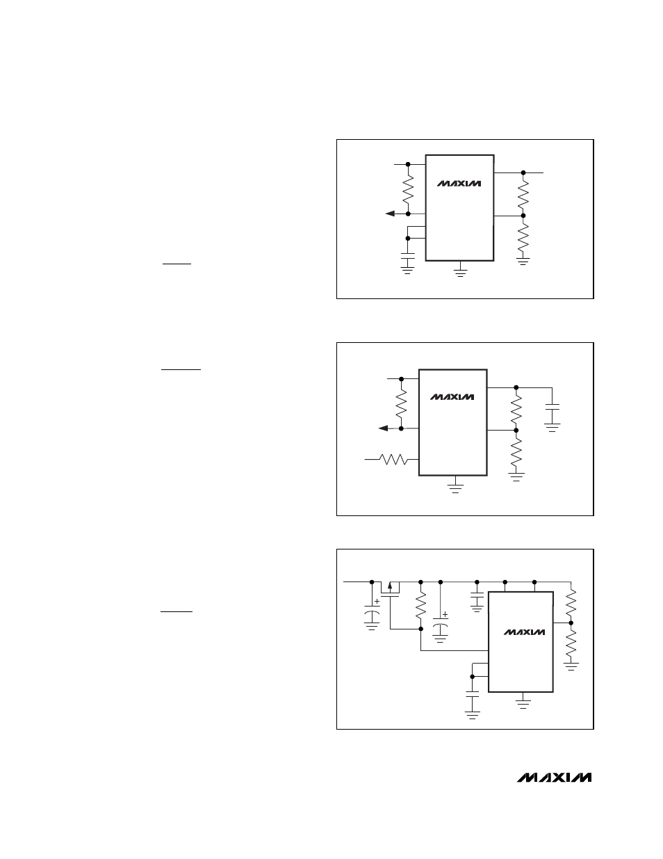
The low-battery comparator can also be used to moni-
tor the output voltage, as shown in Figure 5.
To set the low-battery threshold to a voltage below the
1.25V reference, insert a resistor divider between REF
and LBN, and connect the battery to the LBP input
through a 10k
Ω
current-limiting resistor (Figure 6). The
equation for setting the resistors for the low-battery
threshold is then as follows:
Alternatively, the low-battery comparator can be used
to check the output voltage or to control the load direct-
ly on POUT during start-up (Figure 7). Use the following
equation to set the resistor values:
where V
OUT,TH
is the desired output voltage trip point
and V
LBP
is connected to the reference or 1.25V.
Reference
The MAX1705/MAX1706 have an internal 1.250V, 1%
bandgap reference. Connect a 0.33µF bypass capaci-
tor to GND within 0.2in. (5mm) of the REF pin. REF can
source up to 50µA of external load current.
_________________ Design Procedure
Setting the Output Voltages
Set the step-up converter output voltage between 2.5V
and 5.5V by connecting a resistor voltage-divider to FB
from OUT to GND, as shown in Figure 8. The resistor
values are then as follows:
where V
FB
, the step-up regulator feedback setpoint, is
1.233V. Since the input bias current into FB is less than
50nA, R2 can have a large value (such as 270k
Ω
or
less) without sacrificing accuracy. Connect the resistor
voltage-divider as close to the IC as possible, within
0.2in. (5mm) of the FB pin.
Alternatively, set the step-up converter output to track
the linear regulator by 300mV. To accomplish this, set
TRACK to OUT.
R
R
V
V
POUT
FB
1
2
=
- 1
R
R
V
V
OUT TH
LBP
5
6
,
=
- 1
R
R
V
V
REF
IN TH
5
6
,
=
- 1
MAX1705
MAX1706
LBO
REF
LBN
POUT
GND
R5
R6
0.33
µ
F
LDO
LBP
MAX1705
MAX1706
LBN
LBO
LBP
POUT
REF
GND
R5
R6
BATTERY
VOLTAGE
R8
10k
0.33
µ
F
270k
MAX1705
MAX1706
LBP
LBO
LBN
0.33
µ
F
OUT
POUT
REF
GND
R5
R6
P
C3
0.1
µ
F
C4
C5
STEP-UP OUTPUT
Figure 5. Using the Low-Battery Comparator to Sense
the Output Voltage
Figure 6. Detecting Battery Voltages Below 1.25V
Figure 7. Using the Low-Battery Comparator for Load Control
During Start-Up