Max2338 triple/dual-mode cdma lna/mixers, Ac electrical characteristics (continued) – Rainbow Electronics MAX2338 User Manual
Page 4
MAX2338
Triple/Dual-Mode CDMA LNA/Mixers
4
_______________________________________________________________________________________
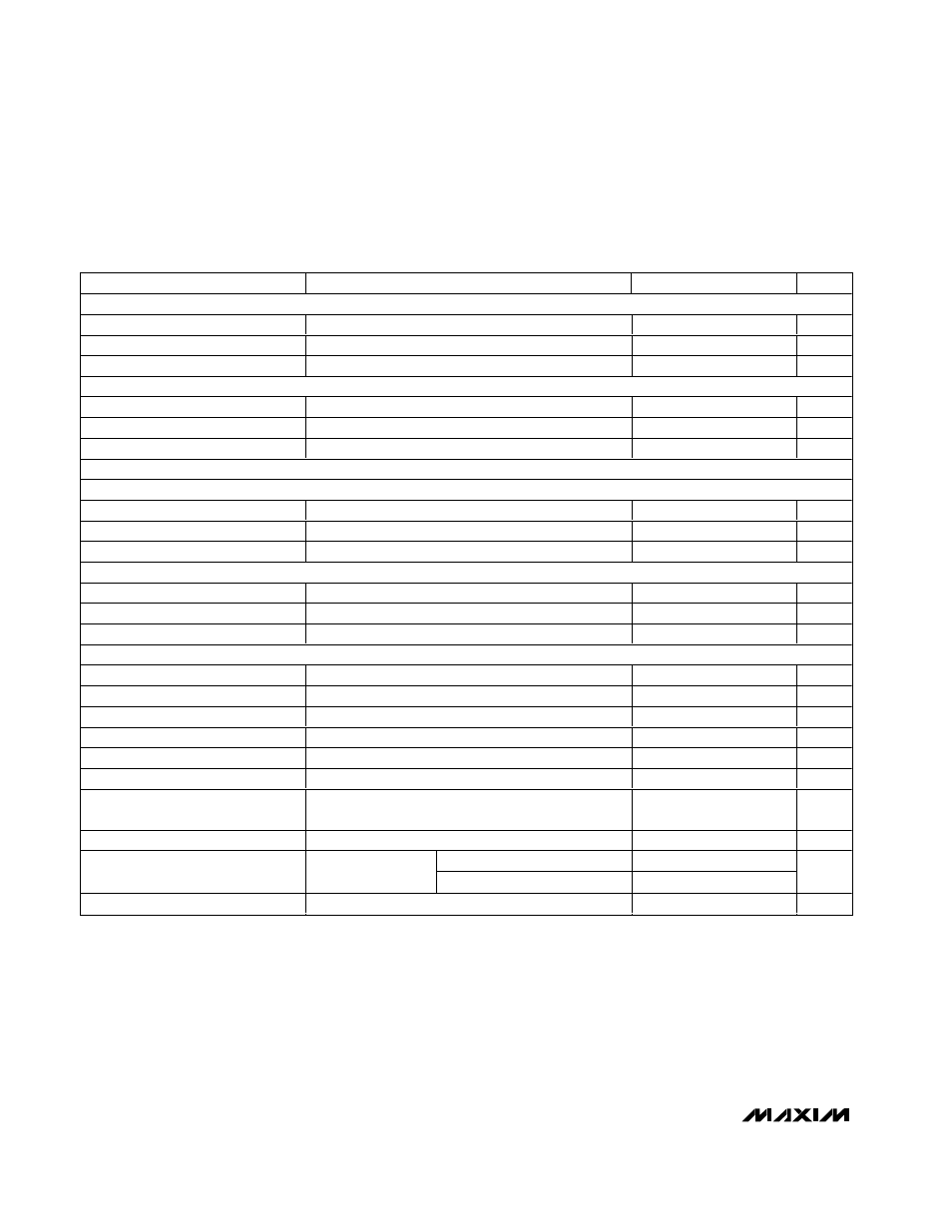
PARAMETER
CONDITIONS
MIN
TYP
MAX
UNITS
HIGH-GAIN, LOW-LINEARITY IDLE MODE
Gain (Note 2)
10.1
13
16
dB
Noise Figure (Note 3)
T
A
= +25
°C
7.3
9.0
dB
IIP3 (Notes 3, 4)
1.4
3.5
dBm
FM MODE
Gain (Note 2)
6.0
8.8
11.1
dB
Noise Figure (Note 3)
T
A
= +25
°C
8.7
11.0
dB
IIP3 (Note 4)
1.4
3.4
dBm
PCS MIXER PERFORMANCE
CDMA HIGH-GAIN, HIGH-LINEARITY MODE
Gain (Note 2)
11.7
14.5
17
dB
Noise Figure (Note 3)
T
A
= +25
°C
7.8
9.0
dB
IIP3 (Notes 3, 5)
3.5
7.5
dBm
HIGH-GAIN, LOW-LINEARITY MODE
Gain (Note 2)
11.2
14
16.2
dB
Noise Figure (Note 3)
T
A
= +25
°C
7.2
9.0
dB
IIP3 (Note 5)
0.5
2.5
dBm
ALL MODES
Mixer Output 1dB Compression
-1
dBm
4 x 5 Suppression (Note 6)
>45
dB
2 x 2 Inp ut Inter cep t P oi nt ( N otes 3, 7)
25
33
dBm
LO Output Level (Note 3)
Into 50
Ω or 100Ω load, BUFFEN = HIGH
-12
-6
dBm
LO Output Leakage
BUFFEN = LOW
-35
dBm
LO E m i ssi on at P C S LN A Inp ut P or t
-55
dBm
LO Emission at Cellular LNA Input
Port
-55
dBm
LO Output Harmonic Suppression
BUFFEN = HIGH
-15
dBc
PCS band, 80MHz below LO
-161
LO Output Noise Power
BUFFEN = HIGH
C ell ul ar b and , 45M Hz b el ow LO
-161
dBm/Hz
RF Ports Return Loss
All active RF ports including 2-element matching
10
dB
AC ELECTRICAL CHARACTERISTICS (continued)
(MAX2338 EV kit, V
CC
= +2.7V to +3.3V, f
PLNAIN
= f
PMIXIN
= 1930MHz to 1990MHz, f
CLNAIN
= f
CMIXIN
= 869MHz to 894MHz, f
IF
=
183MHz, high side LO, LO/2 = LOW. All ports matched to 50
Ω, R
RLNA
= R
RBIAS
= 24k
Ω, T
A
= -40°C to +85°C. Typical values are at
T
A
= +25°C, V
CC
= +3.0V, unless otherwise noted.)
Note 1: Operation over this frequency range may require the ports to be rematched for the desired operating frequency.
Note 2: MIN guaranteed by production test, MAX guaranteed by design and characterization.
Note 3: Guaranteed by design and device characterization.
Note 4: Two-tone IIP3. Tested at f
RF1
= 880MHz, f
RF2
= 880.9MHz, and power = -25dBm/tone.
Note 5: Two-tone IIP3. Tested at f
RF1
= 1960MHz, f
RF2
= 1961.25MHz, and power = -25dBm/tone.
Note 6: F
LO
= 1064MHZ, f
RF1
= 887.8MHz at -30dBm, f
RF2
= 881MHz at -100dBm. Performance is measured as P
IF
due to
RF1 - P
IF
due to RF2.
Note 7: F
LO
= 2143MHz, f
RF1
= 2051.5MHz at -35dBm, f
RF2
= 1960MHz at -100dBm. Performance is measured as P
IF
due to
RF1 - P
IF
due to RF2.