Ac electrical characteristics (continued) – Rainbow Electronics MAX2327 User Manual
Page 6
MAX2320/21/22/24/26/27
Adjustable, High-Linearity,
SiGe Dual-Band LNA/Mixer ICs
6
_______________________________________________________________________________________
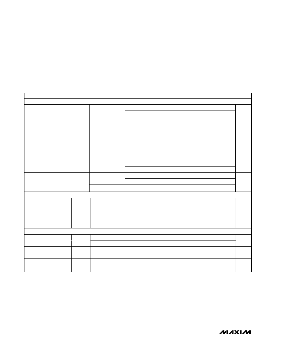
AC ELECTRICAL CHARACTERISTICS (continued)
(MAX232_ EV kit, V
CC
= +2.75V, f
LNAINH
= f
MIXINH
= 1960MHz, f
LNAINL
= f
MIXINL
= 881MHz, f
LOLIN
= 1091MHz (digital mode), f
LOLIN
=
991MHz (FM mode), f
LOHIN
= 1750MHz (MAX2320, MAX2322 with LOX2 = low, MAX2326 with BAND = low, MAX2327), f
LLOHIN
=
1085MHz (MAX2321 with BAND = low, MAX2322 with LOX2 = high), f
LOHIN
= 1091MHz (MAX2321 with BAND = high), f
LOHIN
=
2182MHz (MAX2326 with BAND = high), LO input power = -7dBm (MAX2320/MAX2326), 50
Ω system, T
A
= +25
°C, unless otherwise
noted.) (Note 2)
Note 1: See Tables 1–5 for operational mode selection.
Note 2: A total of 36 devices from 3 different wafer lots are used to determine the standard deviation. The lots were selected to rep-
resent worst-case process conditions.
Note 3: Operation is characterized for the frequencies specified in the conditions; for other frequencies in the band, see Tables 8–12
for LNA and mixer S parameters.
Note 4: Guaranteed by design, characterization, and production functional test.
Note 5: Guaranteed by design and characterization.
Note 6: For cellular band, RF inputs are -25dBm each tone at 881MHz and 882MHz, f
LO
= 1091MHz. For PCS band, RF inputs are
-25dBm each tone at 1960MHz and 1961MHz, f
LO
= 2170MHz. For IIP3 vs. I
CC
trade-off, see Typical Operating
Characteristics.
PARAMETER
SYMBOL
CONDITIONS
MIN
-3
σ
TYP
+3
σ
MAX
UNITS
HIGH-GAIN, LOW-LINEARITY, AND LOW-GAIN MODES (Note 1)
Without doubler
10.6
11.3
12
12.1
12.8
PCS
With doubler
10.2
10.8
11.5
12.4
13.1
Gain (Note 4)
G
Cellular Band
11.2
12.1
13
13.8
14.7
dB
PCS
±1
±1
Gain Variation Over
Temperature Relative
to +25
°C
T
A
= -40
°C to
+85
°C
Cellular
±1
±1
dB
Without doubler
7.2
7.5
7.6
PCS
With doubler
(Note 7)
10.5
12
13.4
Without divider
7
7.2
7.6
Noise Figure
NF
Cellular
With divider
7.5
7.7
8.1
dB
Without doubler
+1
PCS
With doubler
+2.2
Input Third-Order
Intercept
IIP3
Cellular
+1.0
dBm
FM MODE (Note 1)
T
A
= +25
°C
9.7
10.4
11.2
11.9
12.7
Gain (Note 4)
G
T
A
= -40
°C to +85°C
7.8
9.0
11.2
14.0
15.4
dB
Noise Figure
NF
10.6
11.1
11.5
dB
Input Third-Order
Intercept (Notes 5, 6)
IIP3
T
A
= -40
°C to +85°C
2.3
3.2
4.9
dBm
LO BUFFER PERFORMANCE (BUFFEN = HIGH)
Load = 100
Ω pullup resistor
-12
LO Output Level
BUFFEN = GND
-44
dBm
LO_OUT Even Harmonic
Distortion
-31
dBc
LO Emissions at LNA
Input Port
Interstage filter rejection = 20dB
-50
dBm