Pin description (continued) – Rainbow Electronics MAX2327 User Manual
Page 14
MAX2320/21/22/24/26/27
Adjustable, High-Linearity,
SiGe Dual-Band LNA/Mixer ICs
14
______________________________________________________________________________________
PIN
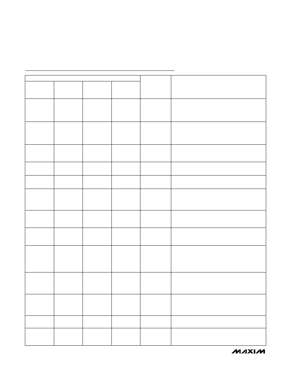
Pin Description (continued)
MAX2320
MAX2321
MAX2326
MAX2322
NAME
FUNCTION
MAX2324
MAX2327
11
11
—
High-Frequency LO Buffer Output. Open-collec-
tor output requires pull-up inductor or pull-up
resistor of 100
Ω or less. Reactive match to the
load delivers maximum power.
LOHOUT
11
—
12
12
—
13
13
FM Mixer Output. Requires a pull-up inductor to
V
CC
and a series capacitor as part of the match-
ing network.
FMOUT
13
Low-Frequency LO Buffer Output. Open-collec-
tor output requires pull-up inductor or pull-up
resistor of 100
Ω or less. Reactive match to the
load delivers maximum power.
LOLOUT
12
13
—
—
14
14
14
Power Supply. Bypass with a 1000pF capacitor
as close to the pin as possible.
V
CC
14
15
15
15
16, 17
—
16, 17
CDMA Mixer Differential Outputs. Require pull-
up inductors and series capacitors as part of the
matching network.
CDMA-,
CDMA+
16, 17
LO Output Buffer Enable. The LO buffers are
controlled separately from the rest of the IC. Drive
BUFFEN high to power up the LO output buffer
associated with the selected LO input port.
BUFFEN
15
LO Doubler Logic Input. Drive LOX2 high to
enable the LO doubler.
LOX2
—
18
18
18
—
19
19
Low-Band Mixer Input. Requires a blocking
capacitor and a matching network. The capaci-
tor may be used as part of the matching net-
work.
MIXINL
19
20
20
—
2, 5, 9, 12,
19
3
1, 10, 11, 20
No Connection. Do not make any connection to
these pins.
N.C.
—
High-Band Mixer Input. Requires a blocking
capacitor and a matching network. The capaci-
tor may be used as part of the matching net-
work.
MIXINH
20
Bias-Setting Resistor Connection. For nominal
bias, connect 20k
Ω resistor to ground. The resis-
tor value controls the digital LNA’s linearity in
low-gain, digital, or FM mode, and controls the
mixers in all modes.
RBIAS
18
Slug
Slug
Slug
Ground Reference for RF, DC, and Logic Inputs.
Solder the slug evenly to the board ground
plane.
GND
Slug
—
16, 17
—
Mixer Differential Outputs. Require pull-up
inductors and series capacitors as part of the
matching network.
IFOUT+,
IFOUT-
—
PIN