Pin description – Rainbow Electronics MAX2327 User Manual
Page 13
MAX2320/21/22/24/26/27
Adjustable, High-Linearity,
SiGe Dual-Band LNA/Mixer ICs
______________________________________________________________________________________
13
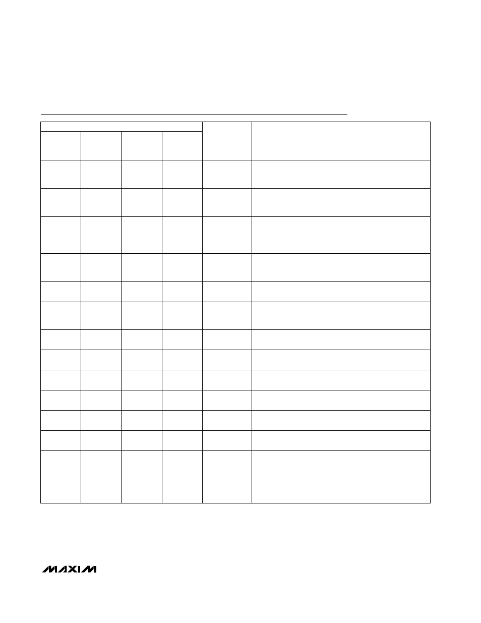
Pin Description
PIN
1
1
—
—
2
2
3
—
3
LNA Bias-Setting Resistor Connection. For nominal bias,
connect a 20k
Ω resistor to ground. The resistor value
controls the LNA’s linearity in high-gain, high-linearity
modes.
RLNA
3
Low-Band LNA Output. Connect a pull-up inductor to
V
CC
and an external series capacitor as part of the
matching network.
LNAOUTL
2
High-Band LNA Output. Connect a pull-up inductor to
V
CC
and an external series capacitor as part of the
matching network.
LNAOUTH
1
4
4
—
—
—
4
Logic Output. Indicates mode of operation. V
MODEOUT
=
high in FM mode.
MODEOUT
—
—
5
5
6
7
6
Shutdown Logic Input. See Detailed Description for con-
trol modes.
SHDN
—
Low-Band RF Input. Requires a blocking capacitor and a
matching network. The capacitor may be used as part of
the matching network.
LNAINL
5
High-Band RF Input. Requires a blocking capacitor and
a matching network. The capacitor may be used as part
of the matching network.
LNAINH
4
—
6
—
7
—
7
Linearity-Select Logic Input. See Detailed Description for
control modes.
LIN
7
8
—
8
—
9
9
Low-Frequency LO Input. Used in FM mode on all parts
and in cellular digital mode for MAX2320/MAX2324.
LOLIN
9
Gain-Select Logic Input. See Detailed Description for
control modes.
GAIN
8
Band-Select Logic Input. See Detailed Description for
control modes.
BAND
6
10
10
—
High-Frequency LO Input. For MAX2321, used in cellular
digital mode and in PCS mode with the doubler active.
For MAX2320/MAX2327, used in PCS mode without the
doubler. For MAX2322, used with or without the doubler.
For MAX2326, used in PCS mode and cellular digital
mode with the divide-by-two.
LOHIN
10
MAX2320
MAX2321
MAX2326
MAX2322
NAME
MAX2324
MAX2327
FUNCTION
—
8
—
Cellular-Band Mode Select Logic Input. See Detailed
Description for control modes.
MODE
—