Rainbow Electronics MAX2327 User Manual
Page 17
MAX2320/21/22/24/26/27
Adjustable, High-Linearity,
SiGe Dual-Band LNA/Mixer ICs
______________________________________________________________________________________
17
Layout Considerations
Keep RF signal lines as short as possible to minimize
losses and radiation. Use high-Q components for the LNA
input matching circuit to achieve the lowest possible
noise figure. At the digital mixer outputs, keep the differ-
ential signal lines together and of equal length to ensure
signal balance. For best gain and noise performance, sol-
der the slug evenly to the board ground plane.
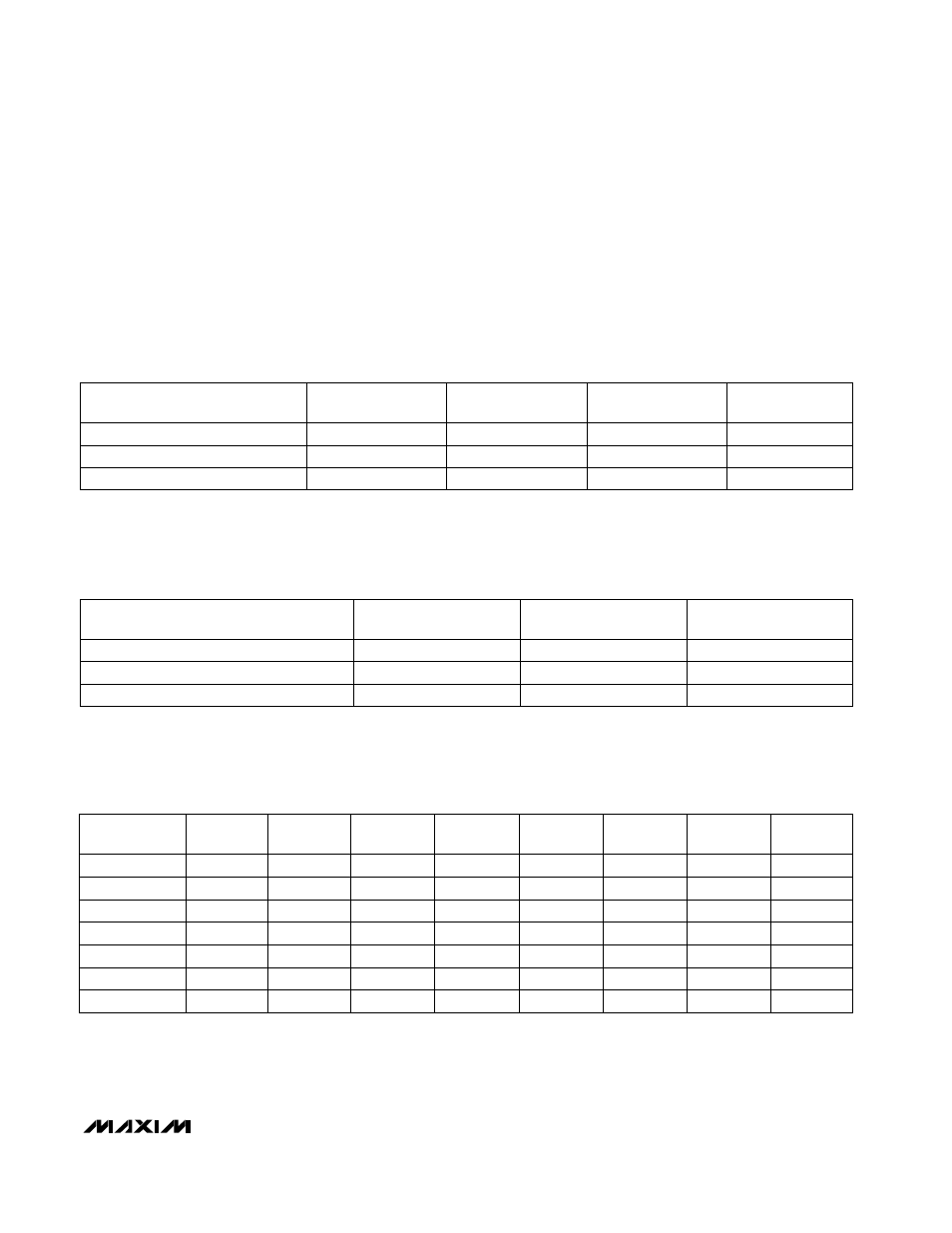
Table 5. Typical Cascaded Performance of Cellular-Band Receiver with 3dB Interstage
Filter Loss
Table 6. Typical Cascaded Performance of PCS-Band Receiver with 3dB Interstage
Filter Loss
PARAMETER
Conversion Power Gain
Noise Figure
Third-Order Input Intercept
HIGH GAIN,
HIGH LINEARITY
25.4dB
2.1dB
-8.9dBm
HIGH GAIN,
LOW LINEARITY
24.5dB
2.3dB
-10.6dBm
LOW GAIN,
HIGH LINEARITY
8.9dB
11.8dB
-6.8dBm
FM
22.7dB
3.3dB
-6.8dBm
-9.3dBm
-7.6dBm
7.1dBm
Third-Order Input Intercept
3.0dB
2.6dB
12.4dB
Noise Figure
PARAMETER
22.5dB
HIGH GAIN,
LOW LINEARITY
24dB
7.5dB
Conversion Power Gain
HIGH GAIN,
HIGH LINEARITY
LOW GAIN
Table 7. Cellular LNA S Parameters in High-Gain, High-Linearity Mode
0.109
59.1
0.669
-40.8
0.496
1000
-90.6
3.3
74.9
0.104
58.3
0.674
-39.3
0.503
950
-88.5
3.5
76.6
0.099
58.8
0.677
-38.3
0.51
900
-86.1
3.7
79.4
0.096
60.1
0.683
-37.6
0.52
850
-83.7
3.88
81.9
0.0908
60
0.689
0.089
60.6
-36.6
0.696
-35.9
0.714
S22
(mag)
-34.7
0.085
S12
(mag)
60.9
S22
(phase)
S12
(phase)
0.534
800
-81.2
4.13
0.548
750
-78.4
84.4
4.39
87.9
4.63
S21
(mag)
92.1
0.579
S11
(mag)
700
-74.8
S21
(phase)
FREQUENCY
(MHz)
S11
(phase)