Table 13a. r, 4576mhz – Rainbow Electronics MAX1400 User Manual
Page 21
MAX1400
+5V, 18-Bit, Low-Power, Multichannel,
Oversampling (Sigma-Delta) ADC
______________________________________________________________________________________
21
External Access to Mux Outputs
The MAX1400 provides access to the switching-net-
work output and the modulator input with the MUXOUT
and ADCIN pins. This allows the user to share a single
high-performance amplifier for additional signal condi-
tioning of all input channels.
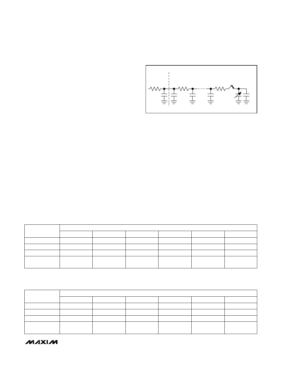
Dynamic Input Impedance at the
Channel Selection Network
When used in unbuffered mode (BUFF = 0), the analog
inputs present a dynamic load to the driving circuitry.
The size of the sampling capacitor and the input sam-
pling frequency (Figure 5) determine the dynamic load
seen by the driving circuitry. The MAX1400 samples at a
constant rate for all gain settings. This provides a maxi-
mum time for the input to settle at a given data rate. The
dynamic load presented by the inputs varies with the
gain setting. For gains of +2V/V, +4V/V, and +8V/V, the
input sampling capacitor increases with the chosen
gain. Gains of +16V/V, +32V/V, +64V/V, and +128V/V
present the same input load as the x8 gain setting.
When designing with the MAX1400, as with any other
switched-capacitor ADC input, consider the advan-
tages and disadvantages of series input resistance. A
series resistor reduces the transient-current impulse to
the external driving amplifier. This improves the amplifi-
er phase margin and reduces the possibility of ringing.
The resistor spreads the transient-load current from the
sampler over time due to the RC time constant of the
circuit. However, an improperly chosen series resis-
tance can hinder performance in fast 16-bit converters.
The settling time of the RC network can limit the speed
at which the converter can operate properly, or reduce
the settling accuracy of the sampler. In practice, this
means ensuring that the RC time constant—resulting
from the product of the driving source impedance and
the capacitance presented by both the MAX1400’s
input and any external capacitances—is sufficiently
small to allow settling to the desired accuracy. Tables
13a–13d summarize the maximum allowable series
resistance vs. external capacitance for each MAX1400
gain setting in order to ensure 16-bit performance in
unbuffered mode.
R
EXT
C
EXT
R
MUX
C
PIN
MUXOUT
ADCIN R
SW
C
ST
C
PIN
C
SAMPLE
C
C
Figure 5. Analog Input, Unbuffered Mode (BUFF = 0)
Table 13a. R
EXT
, C
EXT
Values for Less than 16-Bit Gain Error in Unbuffered (BUFF = 0)
Mode—1x Modulator Sampling Frequency (MF1, MF0 = 00); X2CLK = 0; f
CLKIN
= 2.4576MHz
Table 13b. R
EXT
, C
EXT
Values for Less than 16-Bit Gain Error in Unbuffered (BUFF = 0)
Mode—2x Modulator Sampling Frequency (MF1, MF0 = 00); X2CLK = 0; f
CLKIN
= 2.4576MHz
38
18
38
18
12.5
2
29
16
20
12.7
9.3
8, 16, 32,
64, 128
11.1
12.5
4
1
C
EXT
= 0pF
C
EXT
= 50pF
C
EXT
= 100pF
3.8
2.1
3.8
2.1
0.57
3.5
2.0
3.2
1.8
0.48
0.53
PGA GAIN
0.57
C
EXT
= 500pF
C
EXT
= 1000pF
C
EXT
= 5000pF
EXTERNAL RESISTANCE R
EXT
(k
Ω
)
19
9.2
19
9.2
6.2
2
14
8.0
10
6.3
4.6
8, 16, 32,
64, 128
5.5
6.2
4
1
C
EXT
= 0pF
C
EXT
= 50pF
C
EXT
= 100pF
1.9
1.0
1.9
1.0
0.28
1.7
1.0
1.6
0.92
0.24
0.26
PGA GAIN
0.28
C
EXT
= 500pF
C
EXT
= 1000pF
C
EXT
= 5000pF
EXTERNAL RESISTANCE R
EXT
(k
Ω
)