Rainbow Electronics LM87 User Manual
General description, Features, Key specifications
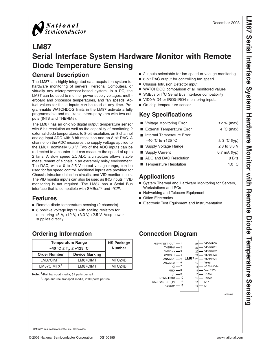
Table of contents
Document Outline
- LM87
- General Description
- Features
- Key Specifications
- Applications
- Ordering Information
- Connection Diagram
- Block Diagram
- Pin Description
- Absolute Maximum Ratings
- Operating Ratings(Notes , )
- DC Electrical Characteristics
- AC Electrical Characteristics
- FIGURE 1. Serial Bus Timing Diagram
- FIGURE 2. ESD Protection Input Structure
- Test Circuit
- Typical Performance Characteristics
- Functional Description
- 1.0 GENERAL DESCRIPTION
- 2.0 INTERFACE
- 3.0 USING THE LM87
- 4.0 ANALOG INPUTS
- 5.0 LAYOUT AND GROUNDING
- 6.0 FAN INPUTS
- 7.0 DAC OUTPUT
- 8.0 TEMPERATURE MEASUREMENT SYSTEM
- 9.0 WATCHDOG LIMIT COMPARISONS AND INTERRUPT STRUCTURE
- FIGURE 11. LM87 Interrupt Structure
- 10.0 RESET# I/O
- 11.0 NAND TREE TESTS
- FIGURE 12. NAND Tree Test Structure
- 12.0 FAN MANUFACTURERS
- 13.0 REGISTERS AND RAM
- 13.1 Address Pointer Register
- 13.2 Address Pointer Index (A7-A0)
- 13.3 Test Register-Address 15h
- 13.4 Channel Mode Register-Address 16h
- 13.5 Configuration Register 1-Address 40h
- 13.6 Interrupt Status Register 1-Address 41h
- 13.7 Interrupt Status Register 2-Address 42h
- 13.8 Interrupt Mask Register 1-Address 43h
- 13.9 Interrupt Mask Register 2-Address 44h
- 13.10 Reserved Register -Address 45h
- 13.11 CI Clear Register-Address 46h
- 13.12 VID0-3/Fan Divisor Register-Address 47h
- 13.13 VID4 Register-Address 49h
- 13.14 Configuration Register 2-Address 4Ah
- 13.15 Interrupt Status Register 1 Mirror-Address 4Ch
- 13.16 Interrupt Status Register 2 Mirror-Address 4Dh
- 13.17 SMBALERT# Enable-Address 80h
- 13.18 Value RAM-Address 19h-3Fh
- Typical Application
- Physical Dimensions