Rainbow Electronics LM87 User Manual
General description, Features, Key specifications
LM87
Serial Interface System Hardware Monitor with Remote
Diode Temperature Sensing
General Description
The LM87 is a highly integrated data acquisition system for
hardware monitoring of servers, Personal Computers, or
virtually any microprocessor-based system. In a PC, the
LM87 can be used to monitor power supply voltages, moth-
erboard and processor temperatures, and fan speeds. Ac-
tual values for these inputs can be read at any time. Pro-
grammable WATCHDOG limits in the LM87 activate a fully
programmable and maskable interrupt system with two out-
puts (INT# and THERM#).
The LM87 has an on-chip digital output temperature sensor
with 8-bit resolution as well as the capability of monitoring 2
external diode temperatures to 8-bit resolution, an 8 channel
analog input ADC with 8-bit resolution and an 8-bit DAC. A
channel on the ADC measures the supply voltage applied to
the LM87, nominally 3.3 V. Two of the ADC inputs can be
redirected to a counter that can measure the speed of up to
2 fans. A slow speed
Σ∆ ADC architecture allows stable
measurement of signals in an extremely noisy environment.
The DAC, with a 0 to 2.5 V output voltage range, can be
used for fan speed control. Additional inputs are provided for
Chassis Intrusion detection circuits, and VID monitor inputs.
The VID monitor inputs can also be used as IRQ inputs if VID
monitoring is not required. The LM87 has a Serial Bus
interface that is compatible with SMBus
™
and I
2
C
™
.
Features
n
Remote diode temperature sensing (2 channels)
n
8 positive voltage inputs with scaling resistors for
monitoring +5 V, +12 V, +3.3 V, +2.5 V, Vccp power
supplies directly
n
2 inputs selectable for fan speed or voltage monitoring
n
8-bit DAC output for controlling fan speed
n
Chassis Intrusion Detector input
n
WATCHDOG comparison of all monitored values
n
SMBus or I
2
C Serial Bus interface compatibility
n
VID0-VID4 or IRQ0-IRQ4 monitoring inputs
n
On chip temperature sensor
Key Specifications
j
Voltage Monitoring Error
±
2 % (max)
j
External Temperature Error
±
4 ˚C (max)
j
Internal Temperature Error
−40 ˚C to +125 ˚C
±
3 ˚C (typ)
j
Supply Voltage Range
2.8 to 3.8 V
j
Supply Current
0.7 mA (typ)
j
ADC and DAC Resolution
8 Bits
j
Temperature Resolution
1.0 ˚C
Applications
n
System Thermal and Hardware Monitoring for Servers,
Workstations and PCs
n
Networking and Telecom Equipment
n
Office Electronics
n
Electronic Test Equipment and Instrumentation
Ordering Information
Temperature Range
NS Package
Number
−40 ˚C
≤ T
A
≤ +125 ˚C
Order Number
Device Marking
LM87CIMT
1
LM87CIMT
MTC24B
LM87CIMTX
2
LM87CIMT
MTC24B
Note:
1
-Rail transport media, 61 parts per rail
2
-Tape and reel transport media, 2500 parts per reel
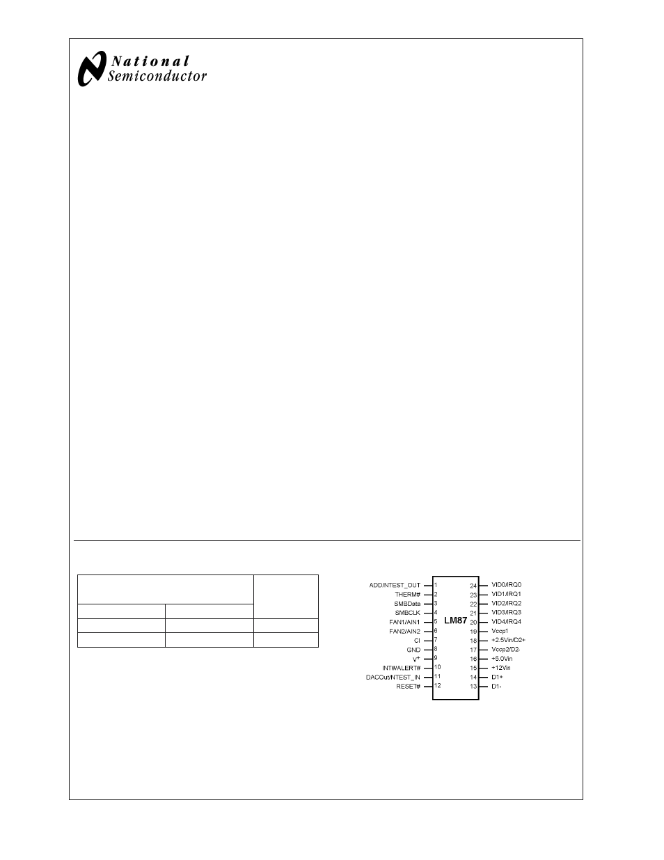
Connection Diagram
10099503
SMBus
™
is a trademark of the Intel Corporation.
December 2003
LM87
Serial
Interface
System
Hardware
Monitor
with
Remote
Diode
T
emperature
Sensing
© 2003 National Semiconductor Corporation
DS100995
www.national.com
Document Outline
- LM87
- General Description
- Features
- Key Specifications
- Applications
- Ordering Information
- Connection Diagram
- Block Diagram
- Pin Description
- Absolute Maximum Ratings
- Operating Ratings(Notes , )
- DC Electrical Characteristics
- AC Electrical Characteristics
- FIGURE 1. Serial Bus Timing Diagram
- FIGURE 2. ESD Protection Input Structure
- Test Circuit
- Typical Performance Characteristics
- Functional Description
- 1.0 GENERAL DESCRIPTION
- 2.0 INTERFACE
- 3.0 USING THE LM87
- 4.0 ANALOG INPUTS
- 5.0 LAYOUT AND GROUNDING
- 6.0 FAN INPUTS
- 7.0 DAC OUTPUT
- 8.0 TEMPERATURE MEASUREMENT SYSTEM
- 9.0 WATCHDOG LIMIT COMPARISONS AND INTERRUPT STRUCTURE
- FIGURE 11. LM87 Interrupt Structure
- 10.0 RESET# I/O
- 11.0 NAND TREE TESTS
- FIGURE 12. NAND Tree Test Structure
- 12.0 FAN MANUFACTURERS
- 13.0 REGISTERS AND RAM
- 13.1 Address Pointer Register
- 13.2 Address Pointer Index (A7-A0)
- 13.3 Test Register-Address 15h
- 13.4 Channel Mode Register-Address 16h
- 13.5 Configuration Register 1-Address 40h
- 13.6 Interrupt Status Register 1-Address 41h
- 13.7 Interrupt Status Register 2-Address 42h
- 13.8 Interrupt Mask Register 1-Address 43h
- 13.9 Interrupt Mask Register 2-Address 44h
- 13.10 Reserved Register -Address 45h
- 13.11 CI Clear Register-Address 46h
- 13.12 VID0-3/Fan Divisor Register-Address 47h
- 13.13 VID4 Register-Address 49h
- 13.14 Configuration Register 2-Address 4Ah
- 13.15 Interrupt Status Register 1 Mirror-Address 4Ch
- 13.16 Interrupt Status Register 2 Mirror-Address 4Dh
- 13.17 SMBALERT# Enable-Address 80h
- 13.18 Value RAM-Address 19h-3Fh
- Typical Application
- Physical Dimensions