2 serial bus interface, Figure 5. serial bus timing, Functional description – Rainbow Electronics LM87 User Manual
Page 12: Lm87
Functional Description
(Continued)
2.2 Serial Bus Interface
The Serial Bus control lines consist of the SMBData (serial
data), SMBCLK (serial clock) and ADD (address) pin. The
LM87 can operate only as a slave. The SMBCLK line only
controls the serial interface, all other clock functions within
LM87 such as the ADC and fan counters are done with a
separate asynchronous internal clock.
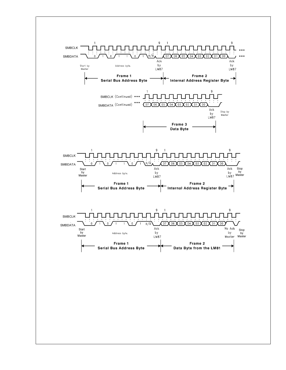
When using the Serial Bus Interface, a write will always
consist of the LM87 Serial Bus Interface Address byte, fol-
lowed by the Internal Address Register byte, then the data
byte. There are two cases for a read:
1.
If the Internal Address Register is known to already be at
the desired Address, simply read the LM87 with the
Serial Bus Interface Address byte, followed by the data
byte read from the LM87.
2.
If the Internal Address Register value is unknown, or if it
is not the desired value, write to the LM87 with the Serial
Bus Interface Address byte, followed by the Internal
Address Register byte. Then restart the Serial Commu-
nication with a Read consisting of the Serial Bus Inter-
face Address byte, followed by the data byte read from
the LM87.
The Serial Bus address of the LM87 is set to 010 11(X)(Y).
All bits, except for X and Y, are fixed and cannot be changed.
The values for X and Y are set by the state of the ADD pin on
10099508
(a) Serial Bus Write to the Internal Address Register followed by the Data Byte
10099509
(b) Serial Bus Write to the Internal Address Register Only
10099510
(c) Serial Bus Read from a Register with the Internal Address Register Preset to Desired Location
FIGURE 5. Serial Bus Timing
LM87
www.national.com
12