Rainbow Electronics MAX867 User Manual
Page 9
MAX866/MAX867
3.3V/5V or Adjustable-Output,
Single-Cell DC-DC Converters
_______________________________________________________________________________________
9
Since the input bias current at FB has a maximum value
of 100nA, large values (10k
Ω
to 300k
Ω
) can be used
for R1 and R2 with no significant accuracy loss. For 1%
error, the current through R1 should be at least 100
times FB’s bias current.
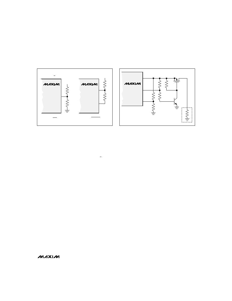
Low-Battery Detection, V
TH
> 1.25V
The MAX866 series contains an on-chip comparator for
low-battery detection. If the voltage at LBI falls below
the regulator’s internal reference voltage (1.25V), LBO
(an open-drain output) sinks current to GND. The low-
battery monitor’s threshold is set by two resistors, R3
and R4 (Figure 3). Set the threshold voltage using the
following equation:
V
TH
R3 = R4
(
____ - 1
)
V
REF
where V
TH
is the desired threshold of the low-battery
detector and V
REF
is the internal 1.25V reference.
Since the LBI current is less than 100nA, large resistor
values (typically 10k
Ω
to 300k
Ω
) can be used for R3
and R4 to minimize loading of the input supply.
When the voltage at LBI is below the internal threshold,
LBO sinks current to GND. Connect a pull-up resistor of
100k
Ω
or more from LBO to OUT when driving CMOS
circuits. When LBI is above the threshold, the LBO out-
put is off. If the low-battery comparator is not used,
connect LBI to V
IN
and leave LBO open.
Low-Battery Detection, V
TH
< 1.25V
When the low-battery detection threshold voltage is
below 1.25V, use the circuit shown on the right in
Figure 3. This circuit uses V
OUT
(3.3V or 5.0V in the
MAX866, adjustable in MAX867) as a reference. The
voltage divider formed by R5 and R6 allows the effec-
tive trip point of V
IN
to be set below 1.25V. R6 is usually
set to approximately 100k
Ω
, and R5 is given by the
formula:
R5 = [R6 x (V
REF
- V
TH
)] / (V
OUT
- V
REF
)
Note that LBI drops below the 1.25V LBI threshold trip
point when either V
IN
or V
OUT
is low.
Since V
OUT
regulation and the LBI threshold are derived
from the same internal voltage reference, they track
together over temperature.
Low-Battery Start-Up
The MAX866/MAX867 are bootstrapped circuits; they
can start under no-load conditions at much lower bat-
tery voltages than under full load. Once started, the out-
put can maintain a moderate load as the battery volt-
age decreases below the start-up voltage (see
Typical
Operating Characteristics). The circuit shown in Figure
4 allows the circuit to start with no load, then uses the
LBI circuit and an external low-threshold P-channel
MOSFET switch to apply the load after the output has
started.
Resistors R7 and R8 are selected to trip the LBI detec-
tor at about 90% of the output voltage. On start-up, LBI
and LBO are low, Q2 is off, and transistor Q1’s gate is
held high by R11. This disconnects the load, allowing
the MAX866 to bootstrap itself at the lowest possible
voltage. When the output reaches its final output volt-
age, LBI and LBO go high, turning on Q2, Q1, and the
load.
Figure 3. Low-Battery Detector Circuits
Figure 4. Low-Voltage Start-Up Circuit
MAX866
LBI
OUT
5
6
R6
R5
V
IN
MAX866
LBI
5
R4
R3
V
IN
FOR V
TH
> 1.25V
R3 = R4
-1
WHERE V
TH
= THE V
IN
TRIP THRESHOLD
WHERE V
TH
= THE V
IN
TRIP THRESHOLD
FOR V
TH
< 1.25V
V
TH
V
REF
(
)
R5 = R6
V
REF
- V
TH
V
OUT
- V
REF
(
)
MAX866
OUT
LBO
LBI
6
4
5
R11
1M
R9
1M
R10
1M
R8
1M
R7
V
OUT
(3.3V/5V)
Q1
MMDFZP02E
Q2
2N3904
(1.25V)
LOAD