Chip topography, Table 2. surface-mount inductor information – Rainbow Electronics MAX867 User Manual
Page 11
tolerate higher output ripple. Values in the 10µF to 47µF
range are recommended.
The equivalent series resistance (ESR) of both bypass
and filter capacitors affects efficiency and output ripple.
Use low-ESR capacitors for best performance, or con-
nect two or more filter capacitors in parallel. Low-ESR,
SMT tantalum capacitors are currently available from
Sprague (595D series) and AVX (TPS series). See
Table 1 for a list of suggested capacitor suppliers.
Rectifier Diode
For optimum performance, a switching Schottky diode
(such as the 1N5817 or MBR0520LTI) is recommended.
Refer to Table 1 for a list of component suppliers. For
low output power applications, a PN-junction switching
diode (such as the 1N4148) will also work well,
although its greater forward voltage drop will reduce
efficiency and raise the start-up voltage.
PC Layout and Grounding
The circuit’s high-frequency operation makes PC layout
important for minimizing ground bounce and noise.
Keep the IC’s GND pin and the ground leads of C1 and
C2 (Figure 2) less than 0.2in (5mm) apart. Also keep all
connections to the FB and LX pins as short as possible.
To maximize output power and efficiency and minimize
output ripple voltage, use a ground plane and solder
the IC’s GND (pin 7) directly to the ground plane.
MAX866/MAX867
3.3V/5V or Adjustable-Output,
Single-Cell DC-DC Converters
______________________________________________________________________________________
11
Table 2. Surface-Mount Inductor Information
MANUFACTURER /PART
INDUCTANCE
(
m
H)
RESISTANCE
(
W
)
RATED CURRENT
(A)
HEIGHT
(mm)
Sumida CD73-331
330
1.5
0.28
3.5
Sumida CD104-331
330
1.1
0.42
4
Murata-Erie LQH4N331K04M00**
330
8.2
0.095
2.6
TDK NLC565050T-331K**
330
4.9
0.14
5
Coilcraft D01608-334
330
2.9
0.16
3.2
Coilcraft DT1608-334
330*
2.9
0.16
3.2
Coilcraft D03316-334
330
0.7
0.6
5.4
Coilcraft DT3316-334
330*
0.7
0.6
5.4
J.W. Miller PM105-331K
330
1.1
0.52
5.4
* Shielded
** Low cost
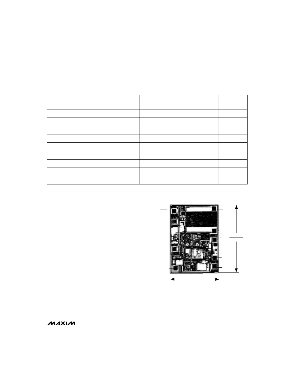
___________________Chip Topography
TRANSISTOR COUNT: 357;
SUBSTRATE IS CONNECTED TO OUT.
GND
LBI
OUT
3/5
OR FB*
REF
LX
0.084"
(2.1336mm)
0.058"
(1.4732mm)
SHDN
LBO
*3/5 FOR MAX866; FB FOR MAX867.