Typical operating characteristics, Electrical characteristics (continued) – Rainbow Electronics MAX867 User Manual
Page 3
MAX866/MAX867
3.3V/5V or Adjustable-Output,
Single-Cell DC-DC Converters
_______________________________________________________________________________________
3
100
0
10
0.01
0.1
1
10
100
1000
EFFICIENCY vs. LOAD CURRENT (V
OUT
= 3.3V)
30
20
MAX866/667-01
LOAD CURRENT (mA)
EFFICIENCY (%)
40
50
60
70
80
90
TOP TO BOTTOM:
V
IN
= 2.0V
V
IN
= 1.5V
V
IN
= 1.25V
V
IN
= 1.0V
V
IN
= 0.75V
V
IN
= 0.5V
L = SUMIDA CD73-331 (330
µ
H, 1.5
Ω
)
100
90
0
0.01
1
0.1
10
100
EFFICIENCY vs. LOAD CURRENT (V
OUT
= 5.0V)
20
MAX866/67-04
LOAD CURRENT (mA)
EFFICIENCY (%)
40
60
80
70
50
30
10
TOP TO BOTTOM:
V
IN
= 2.0V
V
IN
= 1.5V
V
IN
= 1.25V
V
IN
= 1.0V
V
IN
= 0.75V
L = COILCRAFT D01608-334 (330
µ
H, 2.9
Ω
)
100
90
0
0.01
1
0.1
10
100
EFFICIENCY vs. LOAD CURRENT (V
OUT
= 3.3V)
20
MAX866/67-02
LOAD CURRENT (mA)
EFFICIENCY (%)
40
60
80
70
50
30
10
TOP TO BOTTOM:
V
IN
= 2.0V
V
IN
= 1.5V
V
IN
= 1.25V
V
IN
= 1.0V
V
IN
= 0.75V
L = COILCRAFT D01608-334 (330
µ
H, 2.9
Ω
)
100
0
10
0.01
0.1
1
10
100
1000
EFFICIENCY vs. LOAD CURRENT (V
OUT
= 5.0V)
30
20
MAX866/667-03
LOAD CURRENT (mA)
EFFICIENCY (%)
40
50
60
70
80
90
TOP TO BOTTOM:
V
IN
= 2.0V
V
IN
= 1.5V
V
IN
= 1.25V
V
IN
= 1.0V
V
IN
= 0.75V
V
IN
= 0.5V
L = SUMIDA CD73-331 (330
µ
H, 1.5
Ω
)
1200
0
0
0.2
0.4
0.6
0.8 1.0
1.2
1.4 1.6
NO-LOAD BATTERY CURRENT
vs. BATTERY VOLTAGE (V
OUT
= 3.3V)
400
200
1000
MAX866/67-05
BATTERY VOLTAGE (V)
BATTERY CURRENT (
µ
A)
800
600
DECREASING
BATTERY
VOLTAGE
INCREASING
BATTERY
VOLTAGE
4000
0
0
0.2
0.4
0.6
0.8 1.0
1.2
1.4 1.6
NO-LOAD BATTERY CURRENT
vs. BATTERY VOLTAGE (V
OUT
= 5V)
1000
500
3500
MAX866/67-06
BATTERY VOLTAGE (V)
BATTERY CURRENT (
µ
A)
2000
2500
3000
1500
DECREASING
BATTERY
VOLTAGE
INCREASING
BATTERY
VOLTAGE
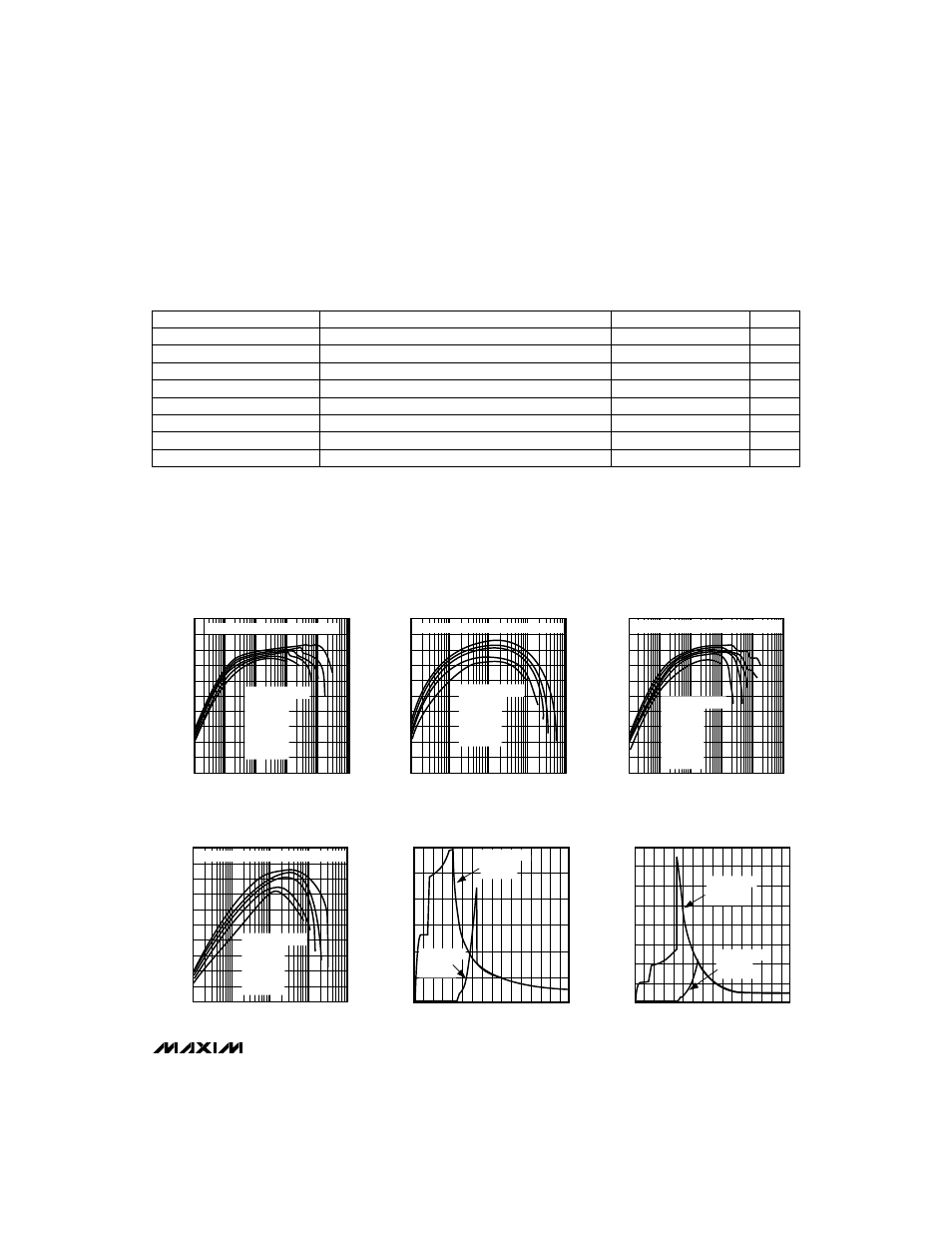
__________________________________________Typical Operating Characteristics
(Circuits of Figure 2, T
A
= +25°C, unless otherwise noted.)
ELECTRICAL CHARACTERISTICS (continued)
(Circuit of Figure 2, V
IN
= 1.2V, I
LOAD
= 0mA, T
A
= +25°C, unless otherwise noted.)
Note 2:
Output current specified with circuit of Figure 2 and CoilCraft D01608-334 inductor for test purposes only. More (or less)
output current can be supplied with other coil types depending on inductance value and coil resistance. See
Typical Operating
Characteristics
for other coil types. Output voltage and output current are guaranteed over this V
IN
operating range once the
device has started up. Actual V
IN
start-up voltage depends on load current.
Note 3:
Output voltage specifications over temperature are guaranteed by design to limits that are 6 sigma from either side of the mean.
Note 4:
Current measured into OUT. V
OUT
is forced to 3.47V to maintain LX off when measuring device current.
PARAMETER
CONDITIONS
MIN
TYP
MAX
UNITS
S
—
H
—
D
—
N
–
, 3/
–
5
–
Input Voltage High
0.32 x V
OUT
V
S
—
H
—
D
—
N
–
, 3/
–
5
–
, FB, LBI Input Current
LBI = 1.5V, FB = 1.5V,
–
S
—
H
—
D
—
N
–
= 0V or 3V, 3/
–
5
–
= 0V or 3V
±40
±100
nA
FB Voltage
MAX867, output in regulation
1.22
1.25
1.28
V
Output Voltage Range
MAX867
2.7
6.0
V
–
S
—
H
—
D
—
N
–
, 3/
–
5
–
Input Voltage Low
0.08 x V
OUT
V
LBO Output Leakage Current
LBO = 5V
1
µA
LBI Input Hysteresis
25
mV
LBO Output Voltage Low
I
SINK
= 2mA, open-drain output
0.4
V