Design procedure – Rainbow Electronics MAX867 User Manual
Page 8
MAX866/MAX867
3.3V/5V or Adjustable-Output,
Single-Cell DC-DC Converters
8
_______________________________________________________________________________________
Voltage Reference
The precision voltage reference is suitable for driving
external loads, such as an analog-to-digital converter.
The voltage-reference output changes less than ±2%
when sourcing up to 250µA and sinking up to 20µA. If
the reference drives an external load, bypass it with
0.22µF to GND. If the reference is unloaded, bypass it
with at least 0.1µF.
Logic Inputs and Outputs
The 3/5 input is internally diode clamped to GND and
OUT, and should not be connected to signals outside
this range. The SHDN input and LBO output (open-
drain) are not clamped to V+ and can be pulled as high
as 7V regardless of the voltage at OUT
.
Do not leave
control inputs (3/5, LBI, or SHDN) floating.
__________________Design Procedure
Output Voltage Selection
For the MAX866, you can select a 3.3V or 5V output volt-
age under logic control, or by tying 3/5 to GND or OUT.
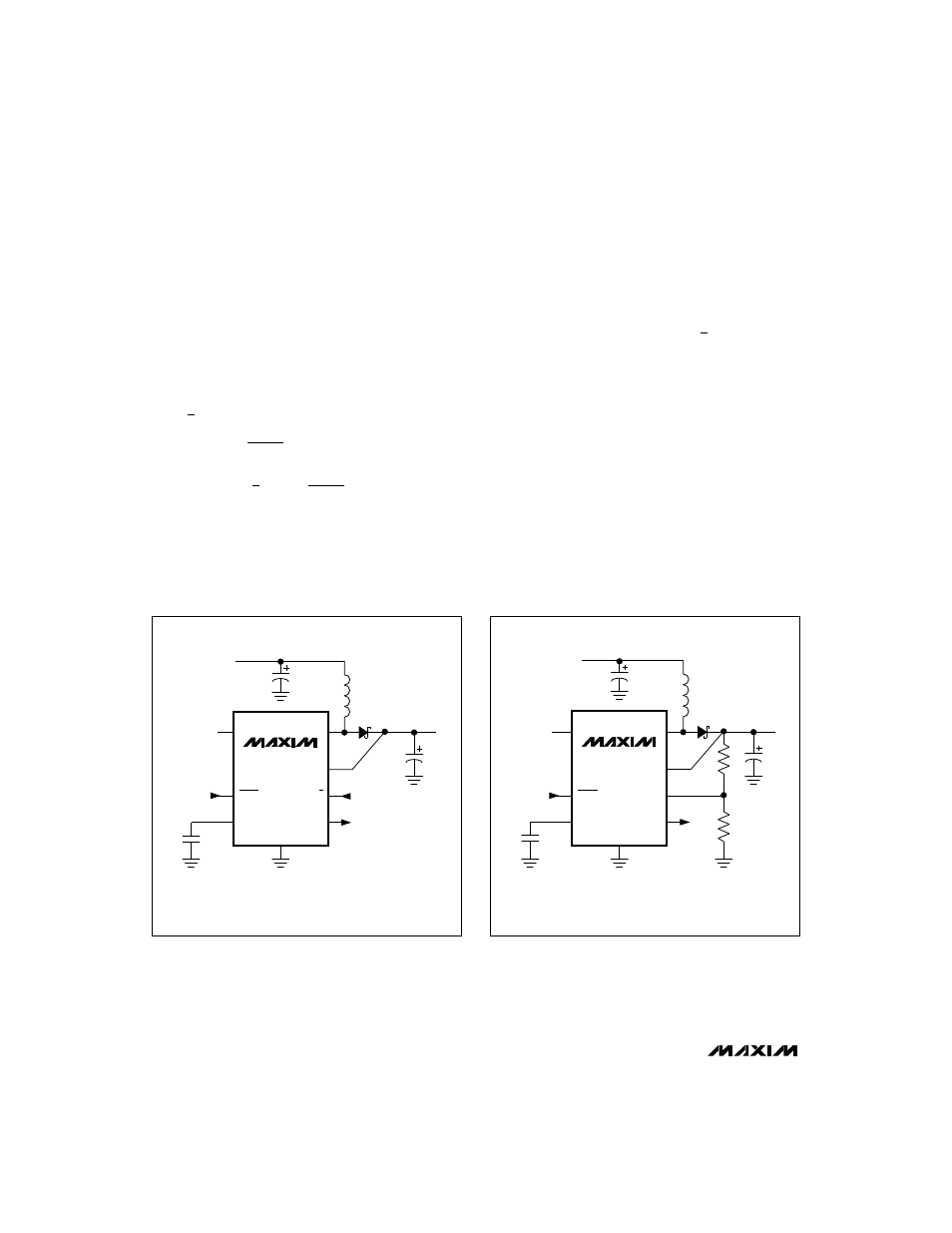
The MAX867’s output voltage is set by two resistors, R1
and R2 (Figure 2b), which form a voltage divider
between the output and FB. Use the following equation
to determine the output voltage:
R1 + R2
V
OUT
= V
REF
(
________
)
R2
where V
REF
= 1.25V.
To simplify resistor selection:
V
OUT
R1 = R2
(
_____ - 1
)
V
REF
C1
47
µ
F
L1
330
µ
F
V
IN
D1
C2
47
µ
F
R1
R2
LX
OUT
FB
LBO
LBI
REF
SHDN
GND
C3
0.1
µ
F
V
OUT
5
1
3
8
6
2
4
7
MAX867
L1 = COILCRAFT DO1608-334
D1 = MOTOROLA MBR0520LTI
C1
47
µ
F
L1
330
µ
H
V
IN
D1
C2
47
µ
F
R1
LX
OUT
3/5
LBO
LBI
REF
SHDN
GND
C3
0.1
µ
F
V
OUT
5
1
3
8
6
2
4
7
MAX866
L1 = COILCRAFT DO1608-334
OUTPUT
SELECT
D1 = MOTOROLA MBR0520LTI
Figure 2b. Standard Application Circuit—Adjustable Output
Voltage
Figure 2a. Standard Application Circuit—Preset Output
Voltage