Typical operating characteristics – Rainbow Electronics MAX2645 User Manual
Page 4
7
8
9
10
11
12
13
14
15
3.0
3.5
4.0
4.5
5.0
5.5
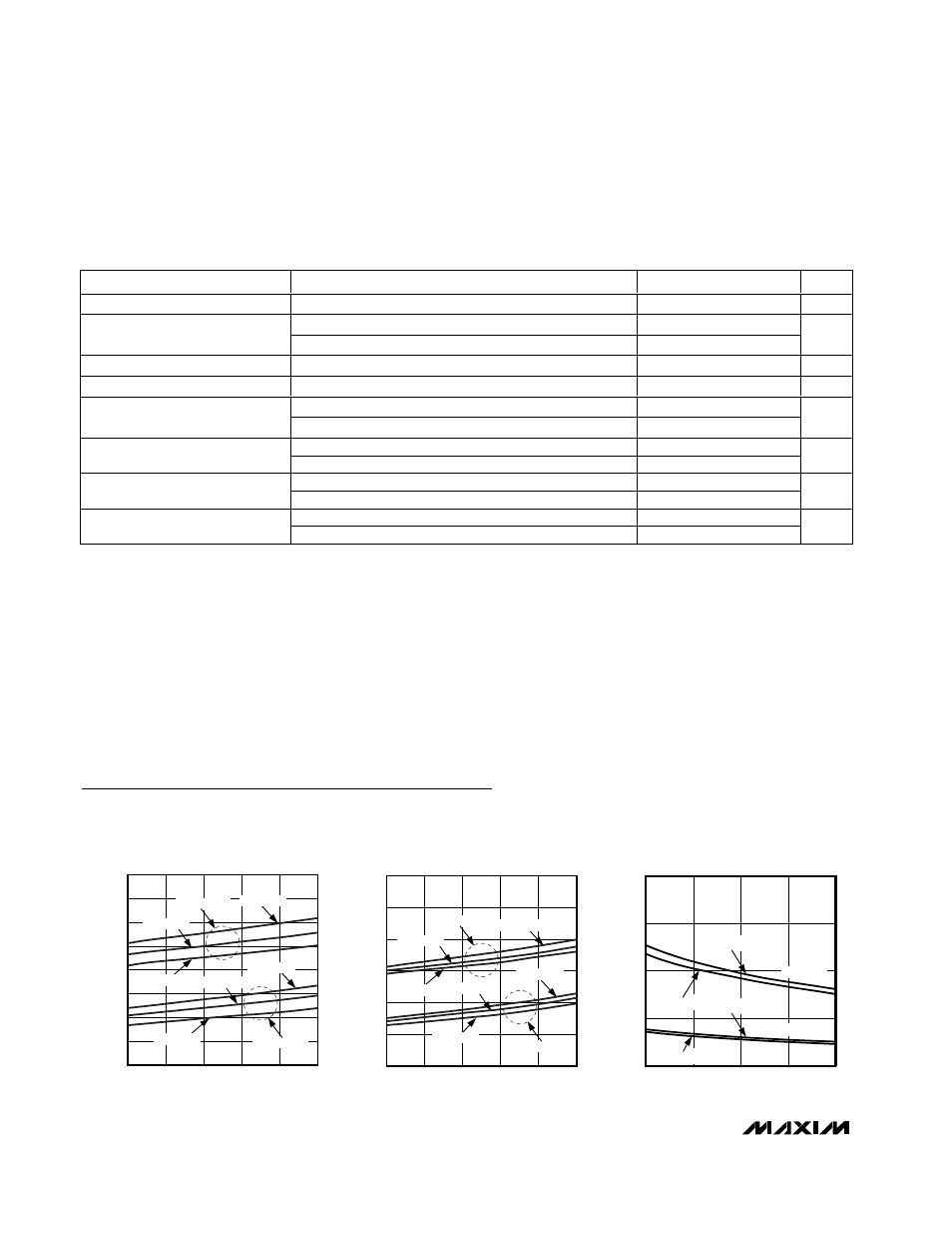
SUPPLY CURRENT vs. SUPPLY VOLTAGE
(HIGH-GAIN MODE)
MAX2645-01
SUPPLY VOLTAGE (V)
SUPPLY CURRENT (mA)
T
A
= +25°C
T
A
= +85°C
T
A
= -40°C
T
A
= +25°C
T
A
= +85°C
R
BIAS
= 20k
Ω
T
A
= -40°C
R
BIAS
= 15k
Ω
2.0
3.0
2.5
4.0
3.5
4.5
5.0
3.0
4.0
3.5
4.5
5.0
5.5
SUPPLY CURRENT vs. SUPPLY VOLTAGE
(LOW-GAIN MODE)
MAX2645-02
SUPPLY VOLTAGE (V)
SUPPLY CURRENT (mA)
T
A
= +85°C
T
A
= +25°C
T
A
= +25°C
T
A
= +85°C
T
A
= -40°C
T
A
= -40°C
R
BIAS
= 15k
Ω
R
BIAS
= 20k
Ω
20
15
10
5
0
15
20
25
SUPPLY CURRENT vs. R
BIAS
MAX2645-03
R
BIAS
(k
Ω)
SUPPLY CURRENT (mA)
HIGH GAIN
LOW GAIN
V
CC
= 3.3V V
CC
= 5V
V
CC
= 5V
V
CC
= 3.3V
Typical Operating Characteristics
(MAX2645 EV kit, V
CC
= +3.3V, R
BIAS
= 20k
Ω, f
RFIN
= 3550MHz, T
A
= +25°C, unless otherwise noted.)
MAX2645
3.4GHz to 3.8GHz SiGe
Low-Noise Amplifier/PA Predriver
4
_______________________________________________________________________________________
AC ELECTRICAL SPECIFICATIONS—PA Predriver Application Circuit
(MAX2645 EV kit, V
CC
= GAIN = SHDN = +3.3V,R
BIAS
= 20k
Ω ±1%, P
RFIN
= -20dBm, f
RFIN
= 3550MHz, Z
o
= 50
Ω,
T
A
= +25°C, unless otherwise noted.)
PARAMETER
CONDITIONS
MIN
TYP
MAX
UNITS
Frequency Range
(Note 1)
3400
3800
MHz
GAIN = V
CC
15.2
Gain
GAIN = GND
-9.7
dB
Gain Variation over Temperature
T
A
= -40
°C to +85°C, GAIN = V
CC
or GND
±0.3
dB
Gain Step
24.9
dB
GAIN = V
CC
(Note 5)
+11.8
Input Third-Order Intercept
GAIN = GND (Note 6)
+16.2
dBm
GAIN = V
CC
-1.8
Input 1dB Compression Point
GAIN = GND
0
dBm
GAIN = V
CC
2.6
Noise Figure
GAIN = GND
16
dB
GAIN = V
CC
25
Reverse Isolation
GAIN = GND
19
dB
Note 1: This is the recommended operating frequency range. Operation outside this frequency range is possible but has not been
characterized. The device is characterized and tested at 3550MHz. For optimum performance at a given frequency, the out-
put matching network must be properly designed. See Applications Information section.
Note 2: Specifications are corrected for board losses (0.25dB at input, 0.25dB at output).
Note 3: Guaranteed by design and characterization.
Note 4: Input IP3 measured with two tones, f
1
= 3550MHz and f
2
= 3551MHz, at -20dBm per tone.
Note 5: Input IP3 measured with two tones, f
1
= 3550MHz and f
2
= 3551MHz, at -12dBm per tone.
Note 6: Specifications are corrected for board losses (0.25dB at input).
Note 7: Time from when GAIN changes state to when output power reaches 1dB of its final value.
Note 8: Time from when SHDN changes state to when output power reaches 1dB of its final value.