Max2670 gps/gnss front-end amplifier, Typical operating characteristics, Ac electrical characteristics (continued) – Rainbow Electronics MAX2670 User Manual
Page 3
����������������������������������������������������������������� Maxim Integrated Products 3
MAX2670
GPS/GNSS Front-End Amplifier
Note 1: T
A
=
+25NC and T
A
= +105NC are guaranteed by production test. At T
A
=
-40NC, the minimum and maximum values are
guaranteed by design and characterization, unless otherwise noted.
Note 2: Measured using the MAX2670 evaluation board with a DC-blocking capacitor at the input of LNA 1.
Note 3: At T
A
= +25NC, the maximum value is guaranteed by design and characterization. Specification is corrected for board
losses on the MAX2670 EV kit.
AC ELECTRICAL CHARACTERISTICS (continued)
(V
CC
= 3.0V to 5.5V, P
IN
= -40dBm, f
IN
= 1575MHz, T
A
= -40NC to +105NC. Typical values are at 5.0V and at T
A
= +25NC. Input
matched to 50I, load = 50I, pin 7 open, unless otherwise noted.) (Note 1)
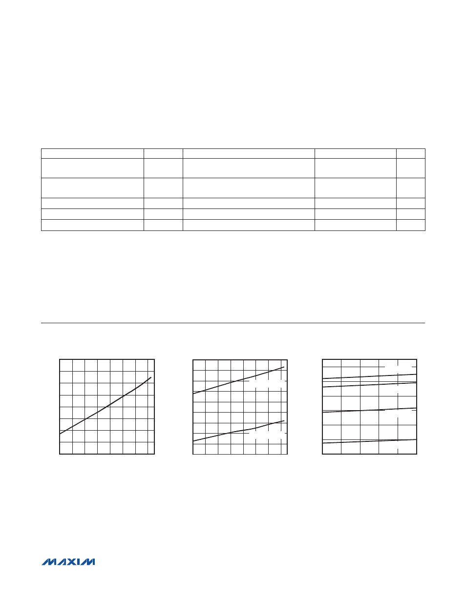
Typical Operating Characteristics
(P
IN
= -40dBm, f
IN
= 1575MHz, inputs and outputs are terminated to 50I, V
CC
= 5.0V, T
A
= +25NC, unless otherwise noted.)
PARAMETER
SYMBOL
CONDITIONS
MIN
TYP
MAX
UNITS
AMP 2 Output Third-Order
Intercept Point
OIP3
Two tones at 1574.5MHz and 1575.5MHz,
-30dBm per tone
16.0
dBm
AMP 2 Output 1dB Compression
Point
5.3
dBm
AMP 2 Input Return Loss
|S
11
|
-21
dB
AMP 2 Output Return Loss
|S
22
|
-8.8
dB
AMP 2 Reverse Isolation
|S
12
|
-25
dB
0.6
0.8
0.7
1.0
0.9
1.1
1.2
1.3
1.4
-40
0
20
-20
40
60
80
100
AMP 1 NOISE FIGURE vs. TEMPERATURE
(WITHOUT EXTERNAL INPUT IMPEDANCE MATCH)
MAX2670 toc01
TEMPERATURE (°C)
NOISE FIGURE (dB)
1.0
2.0
1.5
3.0
2.5
3.5
4.0
4.5
5.5
5.0
-40
0
20
-20
40
60
80
100
AMP 2 NOISE FIGURE vs. TEMPERATURE
MAX2670 toc02
TEMPERATURE (°C)
NOISE FIGURE (dB)
LOW-GAIN MODE
HIGH-GAIN MODE
22.5
21.5
24.5
23.5
26.5
25.5
27.5
3.0
4.0
3.5
4.5
5.0
5.5
SUPPLY VOLTAGE vs. CURRENT
(PIN 7 OPEN)
MAX2670 toc03
SUPPLY VOLTAGE (V)
SUPPLY CURRENT (mA)
T
A
= +105°C
T
A
= +85°C
T
A
= +25°C
T
A
= -40°C