0 functional description, Lm82 – Rainbow Electronics LM82 User Manual
Page 9
1.0 Functional Description
(Continued)
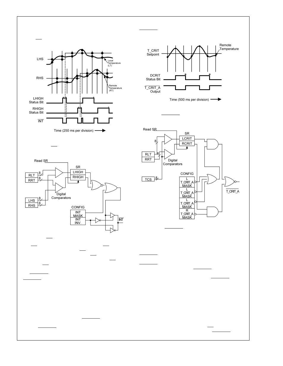
less than or equal to it’s corresponding HIGH setpoint, as
shown in
Figure 4. Figure 5shows a simplified logic diagram
for the INT output and related circuitry.
The INT output can be disabled by setting the INT mask bit,
D7, of the configuration register. INT can be programmed to
be active high or low by the state of the INT inversion bit, D1,
in the configuration register. A “0” would program INT to be
active low. INT is an open-drain output.
1.3 T_CRIT_A OUTPUT and T_CRIT LIMIT
T_CRIT_A is activated when any temperature reading is
greater than the limit preset in the critical temperature set-
point register (T_CRIT), as shown in
Figure 6. The Status
Registers can be read to determine which event caused the
alarm. A bit in the Status Registers is set high to indicate
which temperature reading exceeded the T_CRIT setpoint
temperature and caused the alarm, see
Section 2.3.
Local and remote temperature diodes are sampled in se-
quence by the A/D converter. The T_CRIT_A output and the
Status Register flags are updated at the completion of a con-
version. T_CRIT_A and the Status Register flags are reset
only after the Status Register is read and if a temperature
conversion is below the T_CRIT setpoint, as shown in
Figure
6. Figure 7 shows a simplified logic diagram of the
T_CRIT_A and related circuitry.
Located in the Configuration Register are the mask bits for
each temperature reading, see
Section 2.5. When a mask bit
is set, its corresponding status flag will not propagate to the
T_CRIT_A output, but will still be set in the Status Registers.
Configuration register bits D5 and D3, labled “Remote
T_CRIT_A mask” must be set high before the T_CRIT set-
point is lowered in order for the T_CRIT_A output to function
properly. Setting all four mask bits or programming the
T_CRIT setpoint to 127˚C will disable the T_CRIT_A output.
1.4 POWER ON RESET DEFAULT STATES
LM82 always powers up to these known default states:
1.
Command Register set to 00h
2.
Local Temperature set to 0˚C
3.
Remote Temperature set to 0˚C until the LM82 senses a
diode present between the D+ and D− input pins.
4.
Status Register set to 00h.
5.
Configuration Register set to 00h; INT enabled and all
T_CRIT setpoints enabled to activate T_CRIT_A.
DS101297-14
*
Note: Status Register Bits are reset by a read of Status Register where
bit is located.
FIGURE 4. INT Temperature Response Diagram
DS101297-21
FIGURE 5. INT output related circuitry logic diagram
DS101297-6
*
Note: Status Register Bits are reset by a read of Status Register where
bit is located.
FIGURE 6. T_CRIT_A Temperature Response Diagram
DS101297-20
FIGURE 7. T_CRIT_A output related circuitry logic
diagram
LM82
www.national.com
9