0 functional description – Rainbow Electronics LM82 User Manual
Page 13
1.0 Functional Description
(Continued)
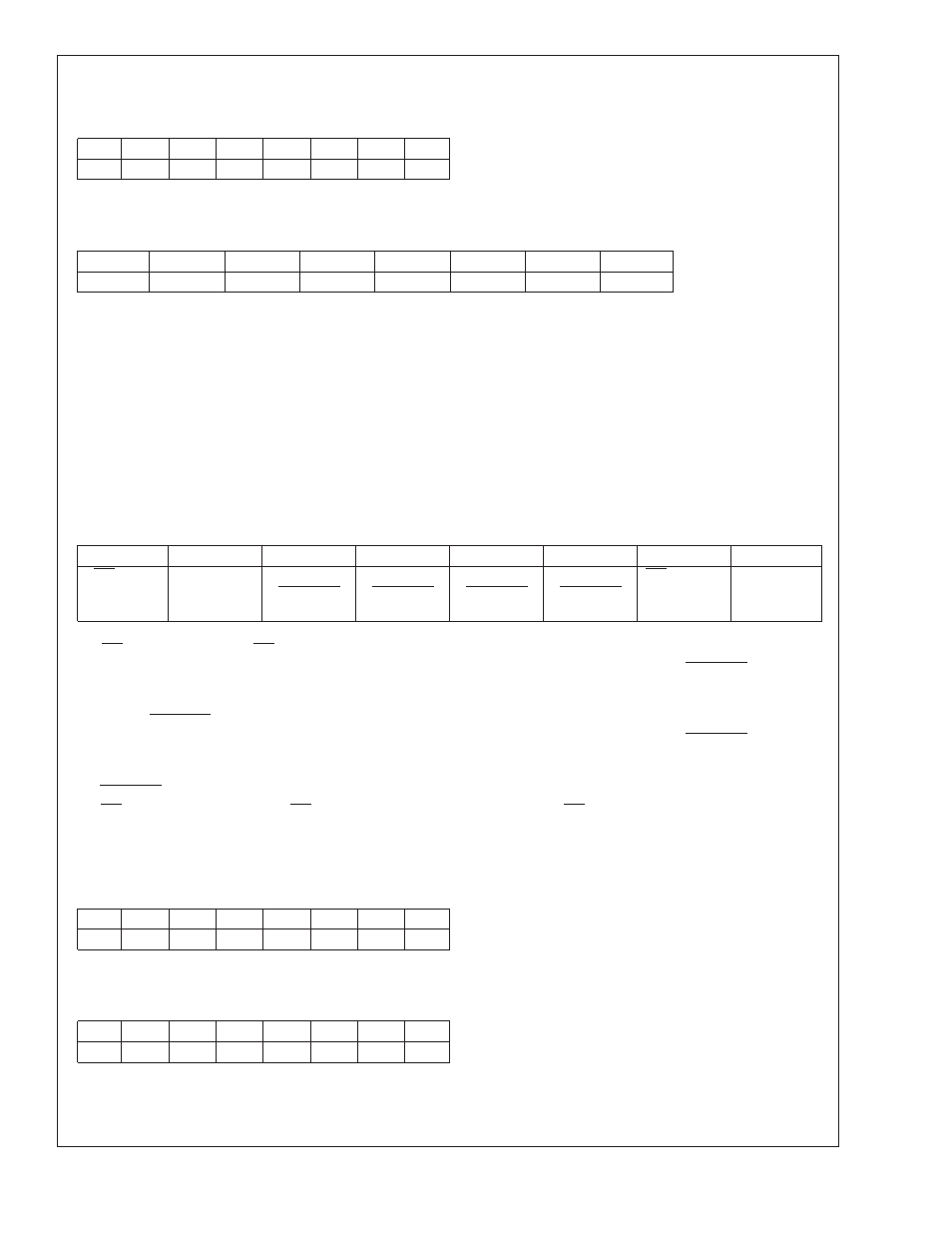
2.2 LOCAL and REMOTE TEMPERATURE REGISTERS (LT, and RT)
(Read Only Address 00h, and 01h):
D7
D6
D5
D4
D3
D2
D1
D0
MSB
Bit 6
Bit 5
Bit 4
Bit 3
Bit 2
Bit 1
LSB
D7–D0: Temperature Data. One LSB = 1˚C. Two’s complement format.
2.3 STATUS REGISTER
(Read Only Address 02h):
D7
D6
D5
D4
D3
D2
D1
D0
0
LHIGH
0
RHIGH
0
OPEN
RCRIT
LCRIT
Power up default is with all bits “0” (zero).
D0: LCRIT: When set to a 1 indicates an Local Critical Temperature alarm.
D1: RCRIT: When set to a 1 indicates a Remote Diode Critical Temperature alarm.
D2: D2OPEN: When set to 1 indicates a Remote Diode disconnect.
D4: D2RHIGH: When set to 1 indicates a Remote Diode HIGH Temperature alarm.
D6: LHIGH: When set to 1 indicates a Local HIGH Temperature alarm.
D7, D5, and D3: These bits are always set to 0 and reserved for future use.
2.4 MANUFACTURERS ID and DIE REVISION(Stepping)
REGISTERS
(Read Address FEh and FFh) Default value 01h for Manufacturers ID(FEh ).
2.5 CONFIGURATION REGISTER
(Read Address 03h/Write Address 09h):
D7
D6
D5
D4
D3
D2
D1
D0
INT mask
0
Remote
T_CRIT_A
mask
Remote
T_CRIT_A
mask
Remote
T_CRIT_A
mask
Local
T_CRIT_A
mask
INT Inversion
0
Power up default is with all bits “0” (zero).
D7: INT mask: When set to 1 INT interrupts are masked.
D5: T_CRIT mask, this bit must be set to a 1 before the T_CRIT setpoint is lowered below 127 in order for T_CRIT_A pin to func-
tion properly.
D4: T_CRIT mask for Remote temperature, when set to 1 a remote temperature reading that exceeds T_CRIT setpoint will not
activate the T_CRIT_A pin.
D3: T_CRIT mask, this bit must be set to a 1 before the T_CRIT setpoint is lowered below 127 in order for T_CRIT_A pin to func-
tion properly.
D2: T_CRIT mask for Local reading, when set to 1 a Local temperature reading that exceeds T_CRIT setpoint will not activate
the T_CRIT_A pin.
D1: INT active state inversion. When INT Inversion is set to a 1 the active state of the INT output will be a logical high. A low would
then select an active state of a logical low.
D6 and D0: These bits are always set to 0 and reserved for future use. A write of 1 will return a 0 when read.
2.6 LOCAL, and REMOTE HIGH SETPOINT REGISTERS (LHS, RHS)
(Read Address 05h, 07h/Write Address 0Bh, 0Dh):
D7
D6
D5
D4
D3
D2
D1
D0
MSB
Bit 6
Bit 5
Bit 4
Bit 3
Bit 2
Bit 1
LSB
D7–D0: HIGH setpoint temperature data. Power up default is LHIGH = RHIGH=127˚C.
2.7 T_CRIT REGISTER (TCS)
(Read Address 42h/Write Address 5Ah):
D7
D6
D5
D4
D3
D2
D1
D0
MSB
Bit 6
Bit 5
Bit 4
Bit 3
Bit 2
Bit 1
LSB
D7–D0: T_CRIT setpoint temperature data. Power up default is T_CRIT = 127˚C.
LM82
www.national.com
13