Pin description – Rainbow Electronics LM82 User Manual
Page 3
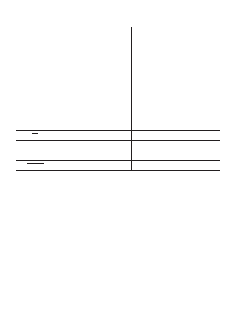
Pin Description
Label
Pin #
Function
Typical Connection
NC
1, 5
floating, unconnected
Left floating. PC board traces may be routed
through the pads for these pins. No restrictions
applied.
V
CC
2
Positive Supply Voltage
Input
DC Voltage from 3.0 V to 3.6 V
D+
3
Diode Current Source
To Diode Anode. Connected to remote discrete
diode junction or to the diode junction on a remote
IC whose die temperature is being sensed. When
not used they should be left floating.
D−
4
Diode Return Current
Sink
To Diode Cathode. Must float when not used.
ADD0–ADD1
10, 6
User-Set SMBus (I
2
C)
Address Inputs
Ground (Low, “0”), V
CC
(High, “1”) or open
(“TRI-LEVEL”)
GND
7, 8
Power Supply Ground
Ground
NC
9, 13, 15
Manufacturing test pins.
Left floating. PC board traces may be routed
through the pads for these pins, although the
components that drive these traces should share
the same supply as the LM82 so that the Absolute
Maximum Rating, Voltage at Any Pin, is not
violated.
INT
11
Interrupt Output,
open-drain
Pull Up Resistor, Controller Interrupt or Alert Line
SMBData
12
SMBus (I
2
C) Serial
Bi-Directional Data Line,
open-drain output
From and to Controller, Pull-Up Resistor
SMBCLK
14
SMBus (I
2
C) Clock Input
From Controller, Pull-Up Resistor
T_CRIT_A
16
Critical Temperature
Alarm, open-drain output
Pull Up Resistor, Controller Interrupt Line or
System Shutdown
LM82
www.national.com
3