0 application hints – Rainbow Electronics LM82 User Manual
Page 16
4.0 Application Hints
(Continued)
6.
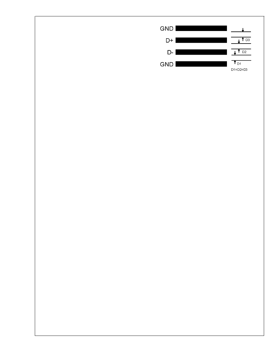
Avoid running diode traces close to or parallel to high
speed digital and bus lines. Diode traces should be kept
at least 2cm. apart from the high speed digital traces.
7.
If it is necessary to cross high speed digital traces, the
diode traces and the high speed digital traces should
cross at a 90 degree angle.
8.
The ideal place to connect the LM82’s GND pin is as
close as possible to the Processors GND associated
with the sense diode.
9.
Leakage current between D+ and GND should be kept
to a minimum. One nano-ampere of leakage can cause
as much as 1˚C of error in the diode temperature read-
ing. Keeping the printed circuit board as clean as pos-
sible will minimize leakage current.
Noise coupling into the digital lines greater than 300mVp-p
(typical hysteresis), overshoot greater than 500mV above
V
CC
, and undershoot less than 500mV below GND, may pre-
vent successful SMBus communication with the LM82. SM-
Bus no acknowledge is the most common symptom, causing
unnecessary traffic on the bus. Although, the SMBus maxi-
mum frequency of communication is rather low (100kHz
max) care still needs to be taken to ensure proper termina-
tion within a system with multiple parts on the bus and long
printed circuit board traces. An R/C lowpass filter with a 3db
corner frequency of about 40MHz has been included on the
LM82’s SMBCLK input. Additional resistance can be added
in series with the SMBData and SMBCLK lines to further
help filter noise and ringing. Minimize noise coupling by
keeping digital traces out of switching power supply areas as
well as ensuring that digital lines containing high speed data
communications cross at right angles to the SMBData and
SMBCLK lines.
DS101297-17
FIGURE 10. Ideal Diode Trace Layout
LM82
www.national.com
16