Pin description – Rainbow Electronics MAX1775 User Manual
Page 9
MAX1775
Dual-Output Step-Down
DC-DC Converter for PDA/Palmtop Computers
_______________________________________________________________________________________
9
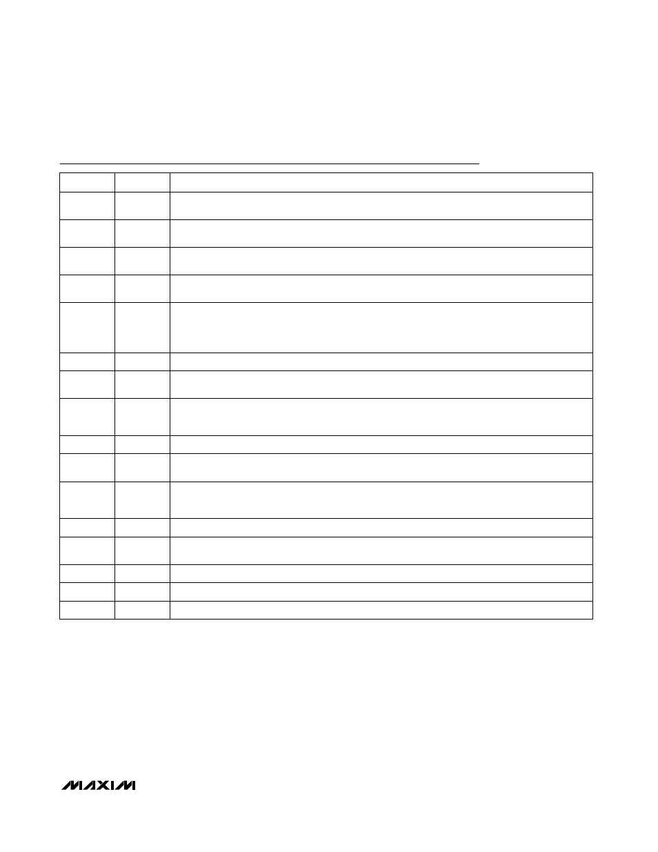
Pin Description
PIN
NAME
FUNCTION
1
SHDNM
Shutdown for Main Regulator. A low voltage on
SHDNM shuts off the main output. For normal
operation, connect
SHDNM to IN.
2
SHDNC
Shutdown for Core Regulator. A low voltage on
SHDNC shuts off the core output. For normal operation,
connect
SHDNC to CVL.
3
PGND
Power Ground. Ground for NDRV and core output synchronous rectifier. Connect all grounds together
close to the IC.
4
NDRV
N-Channel Drive Output. Drives the main output synchronous rectifier MOSFET. NDRV swings between
CVL and PGND.
5
CVL
Low-Side Regulator Bypass. CVL is the output of an internal LDO regulator. This is the internal power
supply for the device control circuitry as well as the N-channel driver. Bypass CVL with a 1.0µF or
greater capacitor to GND. When CS- is above the CVL switchover threshold (2.47V), CVL is powered
from the main output.
6
IN
Power Supply Input
7
PDRV
P-Channel Drive Output. Drives the main output high-side MOSFET switch. PDRV swings between IN
and CVH. The voltage at CVH is regulated at V
IN
- 4.3V unless the input voltage is less than 5.5V.
8
CVH
High-Side Drive Bypass. CVH is the output of an internal LDO regulator with respect to V
IN
. This is the
low-side of the P-channel driver output. Bypass with a 1.0µF capacitor or greater to IN. When the input
voltage is less than +5.5V, CVH is switched to PGND.
9
REF
Reference Voltage Output. Bypass REF to GND with a 0.22µF or greater capacitor.
10
FBM
Main Output Feedback. Connect FBM to a resistive voltage-divider to set main output voltage between
+1.25V to +5.5V.
11
CS+
Main Regulator High-Side Current-Sense Input. Connect the sense resistor between CS+ and CS-.
This voltage is used to set the current limit and to turn off the synchronous rectifier when the inductor
current approaches zero.
12
CS-
Main Regulator Low-Side Current-Sense Input. Connect CS- to the main output.
13
FBC
Core Output Feedback. Connect FBC to a resistive voltage-divider to set core output between +1.0V to
+5.0V.
14
GND
Analog Ground
15
INC
Core Supply Input
16
LXC
Core Converter Switching Node