Design procedure – Rainbow Electronics MAX1775 User Manual
Page 13
MAX1775
Dual-Output Step-Down
DC-DC Converter for PDA/Palmtop Computers
______________________________________________________________________________________
13
Design Procedure
Low-Voltage Configuration
To improve efficiency and conserve board space, the
core regulator operates from low input voltages, taking
advantage of internal low-voltage, low-on-resistance
MOSFETs. When the input voltage remains below 5.5V,
run the core converter directly from the input by con-
necting INC to IN (Figure 1). This configuration takes
advantage of the core’s low-voltage design and
improves efficiency.
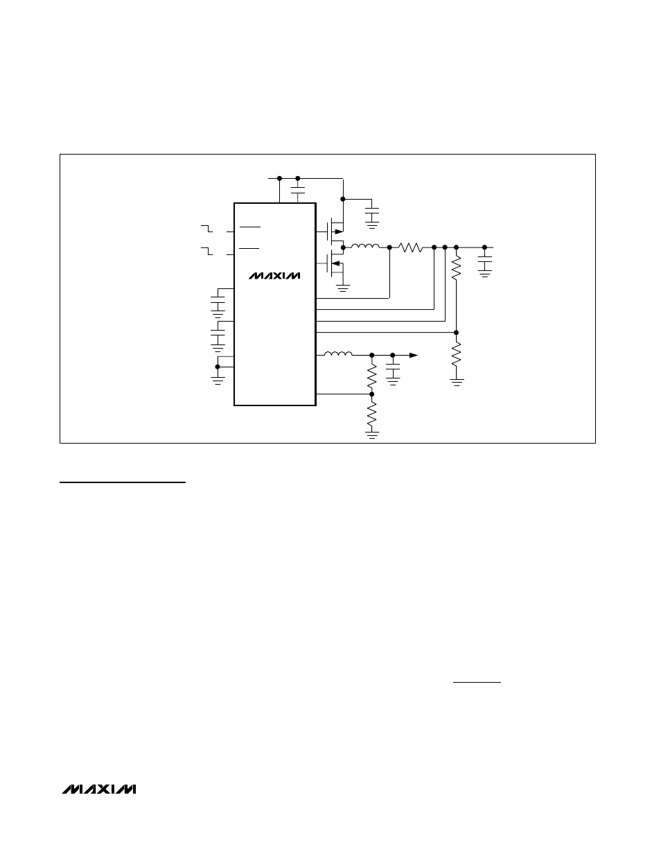
High-Voltage Configuration
For input voltages greater than 5.5V, cascade the main
and core converters by connecting INC to the main out-
put voltage. In this configuration (Figure 4), the core
converter is powered from the main output. Ensure that
the main output can simultaneously supply its load and
the core input current. In this configuration, the main
output voltage must be set above the 2.6V minimum
input voltage of the core converter.
Setting the Output Voltages
The main output voltage may be set from +2.6V and
+5.5V with two external resistors connected as a volt-
age-divider to FBM (Figure 1). Resistor values can be
calculated by the following equation:
R2 = R3
✕
[(V
OUTM
/ V
FBM
) - 1]
where V
FBM
= +1.25V. Choose R3 to be 40k
Ω or less.
The core regulator output is adjustable from +1.0V to
+5.0V through two external resistors connected as a
voltage-divider to FBC (Figure 1). Resistor values can
be calculated through the following equation:
R4 = R5
✕
[(V
OUTC
/ V
FBC
) - 1]
where V
FBC
= +1.0V. Choose R5 to be 30k
Ω or less.
Setting the Current Limit
The main regulator current limit is set externally through
a small current-sense resistor, R1 (Figure 1). The value
of R1 can be calculated by the following equation:
where V
CLM
= 80mV is the current-sense threshold,
and I
OUT
is the current delivered to the output. The
core converter current limit is set internally and cannot
be modified.
R
V
I
CLM
OUT
1
1 3
=
(
)
.
SHDNM
IN
IN 2.7V TO 28V
CVH
M1
M2
C4
47
µF
R1
33m
Ω
R2
R3
R4
R5
CORE
1.8V
1.5A
SHDNC
ON
ON
OFF
OFF
NDRV
CS+
CS-
INC
FBM
LXC
FBC
CVL
REF
PGND
GND
PDRV
C5
22
µF
MAIN
3.3V
2A
C2
1
µF
C3
0.22
µF
L
C
5.4
µH
C1
1
µF
C6
10
µF
6
1
2
5
9
3
14
13
16
10
15
12
11
4
7
8
L
M
10
µH
MAX1775
Figure 4. High Input Voltage Cascaded Configuration