Rainbow Electronics MAX1775 User Manual
Page 11
MAX1775
Dual-Output Step-Down
DC-DC Converter for PDA/Palmtop Computers
______________________________________________________________________________________
11
Regulation Control Scheme
The MAX1775 has a unique operating scheme that
allows PWM operation at medium and high current, with
automatic switching to pulse-skipping mode at lower
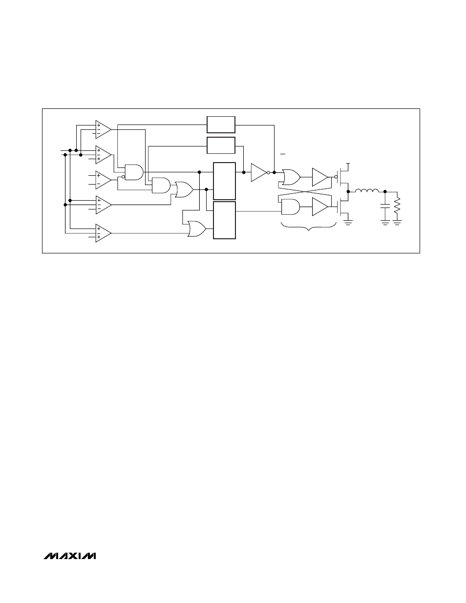
currents to improve light-load efficiency. Figure 2
shows a simplified block diagram.
Under medium- and heavy-load operation, the inductor
current is continuous and the part operates in PWM
mode. In this mode, the switching frequency is set by
either the minimum on-time or the minimum off-time,
depending on the duty cycle. The duty cycle is approx-
imately the output voltage divided by the input voltage.
If the duty cycle is less than 50%, the minimum on-time
controls the frequency; and the frequency is approxi-
mately f
≈ 2.5MHz
✕
D, where D is the duty cycle. If the
duty cycle is greater than 50%, the minimum off-time
sets the frequency; and the frequency is approximately
f
≈ 2.5MHz
✕
(1 - D).
In both cases, the voltage is regulated by the error
comparator. For low duty cycles (<50%), the P-channel
MOSFET turns on for the minimum on-time, causing
fixed-on-time operation. During the P-channel MOSFET
on-time, the output voltage rises. Once the P-channel
MOSFET turns off, the voltage drops to the regulation
threshold, at which time another cycle is initiated. For
high duty cycles (>50%), the P-channel MOSFET
remains off for the minimum off-time, causing fixed off-
time operation. In this case, the P-channel MOSFET
remains on until the output voltage rises to the regula-
tion threshold. Then the P-channel MOSFET turns off for
the minimum off-time, initiating another cycle.
By switching between fixed on-time and fixed off-time
operation, the MAX1775 can operate at high input-out-
put ratios, yet still operate up to 100% duty cycle for
low dropout. Note that when operating in fixed on-time,
the minimum output voltage is regulated; but in fixed
off-time operation, the maximum output voltage is regu-
lated. Thus, as the input voltage drops below approxi-
mately twice the output voltage, a decrease in line
regulation can be expected. The drop in voltage is
approximately V
DROP
≈ V
RIPPLE
. At light output loads,
the inductor current is discontinuous, causing the
MAX1775 to operate at lower frequencies, reducing the
MOSFET gate drive and switching losses. In discontin-
uous mode, under most circumstances, the on-time will
be a fixed minimum of 400ns.
The MAX1775 features four separate current-limit
threshold detectors and a watchdog timer for each of
its step-down converters. In addition to the more com-
mon peak current detector and zero crossing detector,
each converter also provides a valley current detector
(I
VALLEY
) and a minimum current detector (I
MIN
). I
VALLEY
is used to force the inductor current to drop to a lower
level after hitting peak current before allowing the P-
channel MOSFET to turn on. This is a safeguard against
inductor current significantly overshooting above the
peak current when the inductor discharges too slowly
when V
OUT
/L is small. I
MIN
is useful in ensuring that a
minimum current is built up in the inductor before turn-
ing off the P-channel MOSFET. This helps the inductor
to charge the output near dropout when dI/dt is small
(because (V
IN
- V
OUT
) / L is small) to avoid multiple
PSW
NON
PON
V
O
NSW
NONOVERLAP
PROTECTION
Q
S
R
S
R
Q
TONMIN
TOFFMIN
V
VALLEY
V
CLM
V
ZERO
FB
V
REF
V
MIN
CS+
CS-
V
IN
PON
Figure 2. Simplified Control System Block Diagram