Detailed description, Operating modes for the step-down converters, 100% duty cycle and dropout – Rainbow Electronics MAX1775 User Manual
Page 10
MAX1775
Dual-Output Step-Down
DC-DC Converter for PDA/Palmtop Computers
10
______________________________________________________________________________________
Detailed Description
The MAX1775 dual step-down DC-DC converter is
designed to power PDA, palmtop, and subnotebook
computers. Normally, these devices need two separate
power supplies—one for the processor and another
higher voltage supply for the peripheral circuitry. The
MAX1775 provides an adjustable +1.25V to +5.5V main
output designed to power the peripheral circuitry of
PDAs and similar devices. The main output delivers
over 2A output current. The lower voltage core convert-
er has an adjustable +1.0V to +5.0V output, providing
up to 1.5A output current. Both regulators utilize a pro-
prietary regulation scheme, allowing PWM operation at
medium to heavy loads, and automatically switch to
pulse skipping at light loads for improved efficiency.
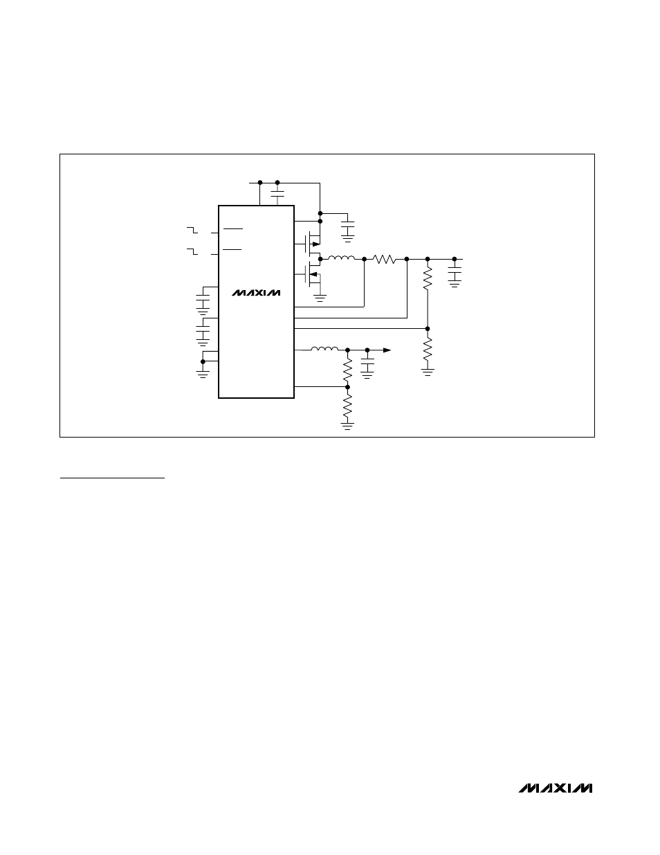
Figure 1 is the typical application circuit.
Operating Modes for the
Step-Down Converters
When delivering low output currents, the MAX1775
operates in discontinuous conduction mode. Current
through the inductor starts at zero, rises above the min-
imum current limit, then ramps down to zero during
each cycle (see Typical Operating Characteristics).
The switch waveform may exhibit ringing, which occurs
at the resonant frequency of the inductor and stray
capacitance, due to the residual energy trapped in the
core when the rectifier MOSFET turns off. This does not
degrade the circuit performance.
When delivering medium-to-high output currents, the
MAX1775 operates in PWM continuous-conduction
mode. In this mode, current always flows through the
inductor and never ramps to zero. The control circuit
adjusts the switch duty cycle to maintain regulation
without exceeding the peak switching current set by
the current-sense resistor.
100% Duty Cycle and Dropout
The MAX1775 operates with a duty cycle up to 100%.
This feature extends the input voltage range by turning
the MOSFET on continuously when the supply voltage
approaches the output voltage. This services the load
when conventional switching regulators with less than
100% duty cycle would fail. Dropout voltage is defined
as the difference between the input and output volt-
ages when the input is low enough for the output to
drop out of regulation. Dropout depends on the MOS-
FET drain-to-source on-resistance, current-sense resis-
tor, and inductor series resistance, and is proportional
to the load current:
Dropout voltage =
I
OUT
✕
[R
DS(ON)
+ R
SENSE
+ R
INDUCTOR
]
SHDNM
IN
IN
2.7V TO 5.5V
CVH
M1
M2
C4
47
µF
R1
33m
Ω
R2
R3
R4
R5
CORE
1.8V
1.5A
MAIN
3.3V
2A
SHDNC
ON
ON
OFF
OFF
NDRV
CS+
CS-
INC
FBM
LXC
FBC
CVL
REF
PGND
GND
PDRV
L
M
5
µH
C5
22
µF
C2
1
µF
C3
0.22
µF
L
C
5.4
µH
C1
1
µF
C6
10
µF
6
1
2
5
9
3
14
13
16
10
12
11
4
7
15
8
MAX1775
Figure 1. Typical Application Circuit (Low Input Voltage)