Chip information – Rainbow Electronics MAX3295 User Manual
Page 10
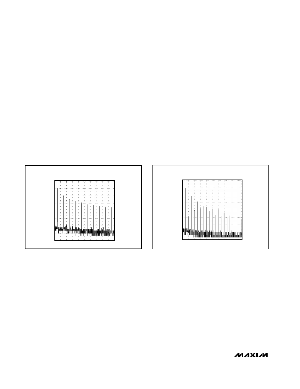
Reduced EMI and Reflections
(MAX3293/MAX3294)
The MAX3293/MAX3294 are slew-rate limited, minimiz-
ing EMI and reducing reflections caused by improperly
terminated cables. Figure 12 shows Fourier analysis of
the MAX3295 transmitting a 125kHz signal. High-fre-
quency harmonics with large amplitudes are evident.
Figure 13 shows the same information, but for the slew-
rate-limited MAX3293, transmitting the same signal.
The high-frequency harmonics have much lower ampli-
tudes, and the potential for EMI is significantly reduced.
To minimize reflections, the line should be terminated at
both ends in its characteristic impedance, and stub
lengths off the main line should be kept as short as
possible. The slew-rate-limited MAX3293 and MAX3294
are more tolerant of imperfect termination.
Driver Output Protection
Two mechanisms prevent excessive output current and
power dissipation caused by faults or by bus contention.
The first, a foldback current limit on the output stage,
provides immediate protection against short circuits over
the whole common-mode voltage range (see the Typical
Operating Characteristics). The second, a thermal-shut-
down circuit, forces the driver outputs into a high-imped-
ance state if the die temperature exceeds +160°C.
MAX3293/MAX3294/MAX3295
20Mbps, +3.3V, SOT23 RS-485/
RS-422 Transmitters
10
______________________________________________________________________________________
Figure 12. Driver Output Waveform and FFT Plot of MAX3295
Transmitting a 125kHz Signal
Figure 13. Driver Output Waveform and FFT Plot of MAX3293
Transmitting a 125kHz Signal
DRIVER OUTPUT WAVEFORM AND
FFT PLOT OF MAX3293
10dB/div
Chip Information
TRANSISTOR COUNT: 263
PROCESS: BiCMOS
DRIVER OUTPUT WAVEFORM AND
FFT PLOT OF MAX3295
10dB/div