Rainbow Electronics MAX1618 User Manual
Page 9
and does not go inactive until the temperature drops
below T
LOW
.
Enable thermostat mode through the configuration reg-
ister (Table 4), with one bit to enable the feature and
another bit to set the output polarity (active high or
active low). The ALERT thermostat comparison is made
after each conversion, or at the end of any SMBus
transaction. For example, if the limit is changed while
the device is in standby mode, the ALERT output
responds correctly according to the last valid A/D
result. Upon entering thermostat mode, the ALERT out-
put is reset so that if the temperature is in the hysteresis
band ALERT initially goes inactive. The power-on reset
(POR) state disables thermostat mode.
Diode Fault Alarm
A continuity fault detector at DXP detects whether the
remote diode has an open-circuit condition, short-cir-
cuit to GND, or short-circuit DXP-to-DXN condition. At
the beginning of each conversion, the diode fault is
checked, and the status byte is updated. This fault
detector is a simple voltage detector; if DXP rises
MAX1618
Remote Temperature Sensor
with SMBus Serial Interface
_______________________________________________________________________________________
9
MAX1618
SMBCLK
ADD0
ADD1
STBY
V
CC
+12V
GND
DXP
DXN
+3V TO +5.5V
SMBUS
SERIAL
INTERFACE
(TO HOST)
2N3904
SMBDATA
ALERT
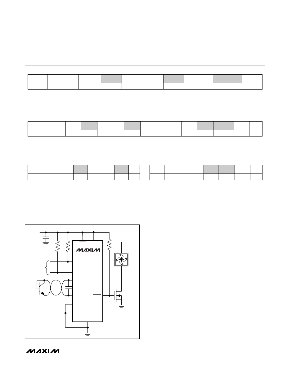
Figure 3. Fan Control Application
Write Byte Format
Read Byte Format
Send Byte Format
Receive Byte Format
Slave Address: equiva-
lent to chip-select line of
a 3-wire interface
Command Byte: selects which
register you are writing to
Data Byte: data goes into the register
set by the command byte (to set
thresholds, configuration masks, and
sampling rate)
Slave Address: equiva-
lent to chip-select line of
a 3-wire interface
Command Byte: selects
which register you are
reading from
Slave Address: repeated
due to change in data-
flow direction
Data Byte: reads from
the register set by the
command byte
Data Byte: writes data to the
register commanded by the
last Read Byte or Write Byte
transmission
Data Byte: reads data from
the register commanded
by the last Read Byte or
Write Byte transmission;
also used for SMBus Alert
Response return address
S = Start condition
Shaded = Slave transmission
P = Stop condition
A
= Not acknowledged
Figure 2. SMBus Protocols
S
ADDRESS
7 bits
WR
ACK
DATA
8 bits
ACK
P
S
ADDRESS
7 bits
WR
ACK
DATA
8 bits
A
P
S
ADDRESS
7 bits
WR
ACK
COMMAND
8 bits
ACK
S
ADDRESS
7 bits
RD
ACK
DATA
8 bits
A
P
S
ADDRESS
7 bits
WR
ACK
8 bits
COMMAND
ACK
8 bits
DATA
ACK
P