Chip information – Rainbow Electronics MAX1618 User Manual
Page 14
MAX1618
Remote Temperature Sensor
with SMBus Serial Interface
14
______________________________________________________________________________________
6) When introducing a thermocouple, make sure that
both the DXP and the DXN paths have matching
thermocouples. In general, PC board-induced ther-
mocouples are not a serious problem. A copper-
solder thermocouple exhibits 3µV/°C, and it takes
approximately 200µV of voltage error at DXP-DXN to
cause a +1°C measurement error, so most parasitic
thermocouple errors are swamped out.
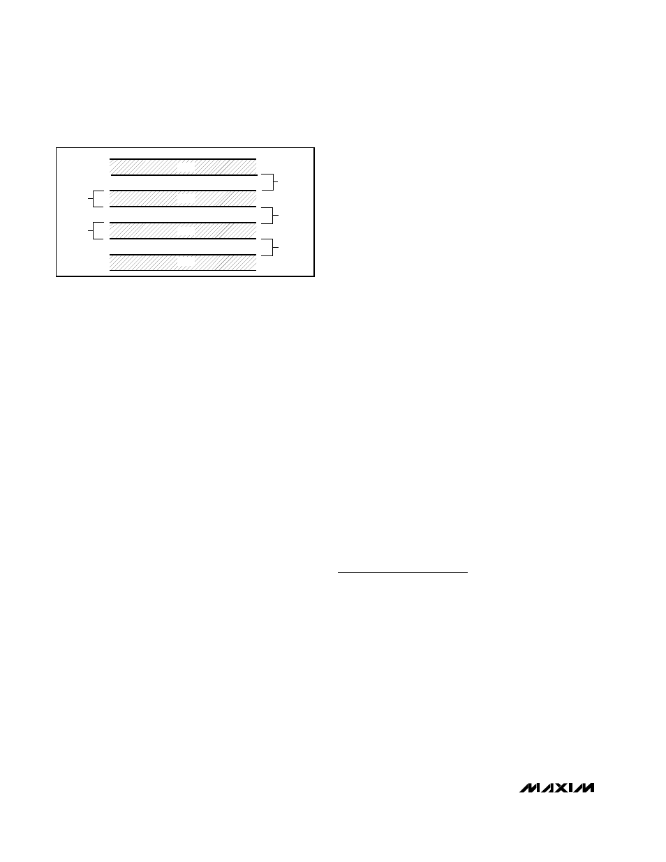
7) Use wide traces. Narrow traces are more inductive
and tend to pick up radiated noise. The 10mil
widths and spacings recommended in Figure 5 are
not absolutely necessary (as they offer only a minor
improvement in leakage and noise), but try to use
them where practical.
8) Note that copper cannot be used as an EMI shield.
Use only ferrous materials such as steel. Placing a
copper ground plane between the DXP-DXN traces
and traces carrying high-frequency noise signals
does not help reduce EMI.
Twisted Pair and Shielded Cables
For remote-sensor distances longer than 8 inches, or in
particularly noisy environments, a twisted pair is recom-
mended. Its practical length is 6 feet to 12 feet (typ)
before noise becomes a problem, as tested in a noisy
electronics laboratory. For longer distances, the best
solution is a shielded twisted pair like that used for audio
microphones. For example, Belden #8451 works well for
distances up to 100 feet in a noisy environment. Connect
the twisted pair to DXP and DXN and the shield to GND,
and leave the shield’s remote end unterminated.
Excess capacitance at DX_ limits practical remote-sen-
sor distances (see Typical Operating Characteristics).
For very long cable runs, the cable's parasitic capaci-
tance often provides noise filtering, so the recommended
2200pF capacitor can often be removed or reduced in
value.
Cable resistance also affects remote-sensor accuracy. A
1
Ω series resistance introduces about +1/2°C error.
Programming Example:
Clock-Throttling Control for CPUs
Listing 1 gives an untested example of pseudocode for
proportional temperature control of Intel mobile CPUs
through a power-management microcontroller. This pro-
gram consists of two main parts: an initialization routine
and an interrupt handler. The initialization routine checks
for SMBus communications problems and sets up the
MAX1618 configuration. The interrupt handler responds
to ALERT signals by reading the current temperature and
setting a CPU clock duty factor proportional to that tem-
perature. The relationship between clock duty and tem-
perature is fixed in a look-up table contained in the
microcontroller code.
Note: Thermal management decisions should be made
based on the latest external temperature obtained from
the MAX1618 rather than the value of the Status Byte.
The MAX1618 responds very quickly to changes in its
environment due to its sensitivity and its small thermal
mass. High and low alarm conditions can exist at the
same time in the Status Byte, because the MAX1618 is
correctly reporting environmental changes around it.
MINIMUM
10 MILS
10 MILS
10 MILS
10 MILS
GND
DXN
DXP
GND
Figure 6. Recommended DXP/DXN PC Traces
Chip Information
TRANSISTOR COUNT: 9911