Typical operating characteristics, Electrical characteristics (continued) – Rainbow Electronics MAX1618 User Manual
Page 4
40
-40
1
100
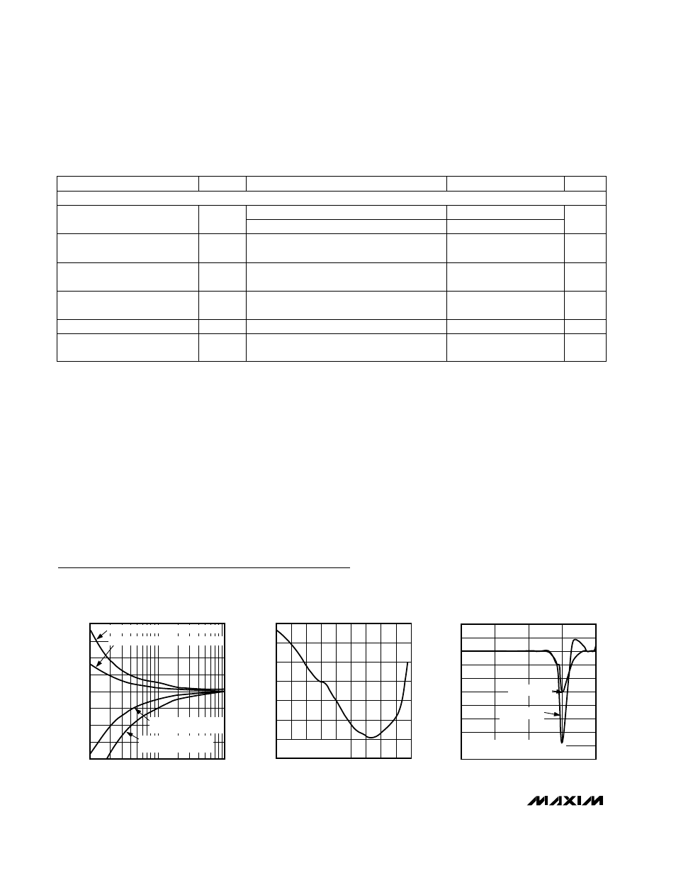
TEMPERATURE ERROR
vs. LEAKAGE RESISTANCE
-20
-30
-10
0
10
20
30
MAX1618 toc01
LEAKAGE RESISTANCE (M
Ω)
TEMPERATURE ERROR (°C)
10
PATH = DXP TO GND AND CONFIG = H00
PATH = DXP TO GND AND CONFIG = H08
PATH = DXP TO V
CC
(5.0V)
AND CONFIG = H08
PATH = DXP TO V
CC
(5.0V)
AND CONFIG = H00
-8
-5
-6
-7
-4
-3
-2
-1
0
1
2
0.005
0.05
0.5
5
50
TEMPERATURE ERROR vs.
POWER-SUPPLY NOISE FREQUENCY
MAX1618 toc03
POWER-SUPPLY NOISE FREQUENCY (MHz)
TEMPERATURE ERROR (
°C)
V
IN
= SQUARE WAVE APPLIED TO
V
CC
WITH NO 0.1
µF V
CC
CAPACITOR
V
IN
= 100mVp
-
p
V
IN
= 250mVp
-
p
Typical Operating Characteristics
(T
A
= +25°C, unless otherwise noted.)
-1.00
0.00
-0.50
1.00
0.50
2.00
1.50
2.50
-55
-15
5
-35
25
45
65
85 105 125
TEMPERATURE ERROR
vs. REMOTE-DIODE TEMPERATURE
MAX1618 toc02
TEMPERATURE (°C)
TEMPERATURE ERROR (
°C)
CENTRAL CMPT3904
RANDOM SAMPLE
MAX1618
Remote Temperature Sensor
with SMBus Serial Interface
4
_______________________________________________________________________________________
ELECTRICAL CHARACTERISTICS (continued)
(V
CC
= +3.3V, configuration byte register = X8h, T
A
= -55°C to +125°C, unless otherwise noted.) (Note 5)
Note 1: Guaranteed, but not 100% tested.
Note 2: A remote diode is any diode-connected transistor from Table 7. T
R
is the junction temperature of the remote diode. See
Remote Diode Selection for remote-diode forward voltage requirements. Temperature specification guaranteed for a diode
with ideality factor (M
TR
= 1.013). Additional error = (1.013/M - 1)
✕
273 + Temp where M = Ideality of remote diode used.
Note 3: The SMBus logic block is a static design that works with clock frequencies down to DC. While slow operation is possible, it
violates the 10kHz minimum clock frequency and SMBus specifications and may monopolize the bus.
Note 4: Note that a transition must internally provide at least a hold time to bridge the undefined region (300ns max) of SMBCLK’s
falling edge.
Note 5: Specifications from -55°C to +125°C are guaranteed by design, not production tested.
CONDITIONS
UNITS
MIN
TYP
MAX
PARAMETER
V
CC
= 3.0V
2.2
STBY, SMBCLK, SMBDATA
Input High Voltage
V
2.4
ALERT forced to 0.4V
mA
1
ALERT Output Low Sink Current
V
CC
= 5.5V
V
CC
= 3.0V to 5.5V
0.8
STBY, SMBCLK, SMBDATA
Input Low Voltage
V
Logic inputs forced to V
CC
or GND
-2
2
STBY, SMBCLK, SMBDATA
Input Current
µA
SMBCLK, SMBDATA forced to 0.6V
6
SMBCLK, SMBDATA Output
Low Sink Current
mA
ALERT forced to 5.5V
µA
1
ALERT Output High Leakage
Current
SMBus INTERFACE