Rainbow Electronics MAX1618 User Manual
Page 13
introduces errors due to the rise time of the switched-
current source.
PC Board Layout
1) Place the MAX1618 as close as practical to the
remote diode. In a noisy environment, such as a
computer motherboard, this distance can be 4 inch-
es to 8 inches (typ) or more, as long as the worst
noise sources (such as CRTs, clock generators,
memory buses, and ISA/PCI buses) are avoided.
2) Do not route the DXP–DXN lines next to the deflec-
tion coils of a CRT. Also, do not route the traces
across a fast memory bus, which can easily
introduce +30°C error, even with good filtering.
Otherwise, most noise sources are fairly benign.
3) Route the DXP and DXN traces parallel and close to
each other, away from any high-voltage traces such
as +12V
DC
. Avoid leakage currents from PC board
contamination. A 20M
Ω leakage path from DXP to
ground causes approximately +1°C error.
4) Connect guard traces to GND on either side of the
DXP-DXN traces (Figure 5). With guard traces in
place, routing near high-voltage traces is no longer
an issue.
5) Route as few vias and crossunders as possible to
minimize copper/solder thermocouple effects.
MAX1618
Remote Temperature Sensor
with SMBus Serial Interface
______________________________________________________________________________________
13
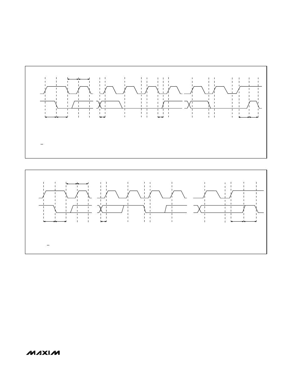
Figure 5. SMBus Read Timing Diagram
Figure 4. SMBus Write Timing Diagram
SMBCLK
A
B
C
D
E
F
G
H
I
J
K
SMBDATA
t
SU:STA
t
HD:STA
t
LOW
t
HIGH
t
SU:DAT
t
HD:DAT
t
SU:STO
t
BUF
A = START CONDITION
B = MSB OF ADDRESS CLOCKED INTO SLAVE
C = LSB OF ADDRESS CLOCKED INTO SLAVE
D = R/W BIT CLOCKED INTO SLAVE
E = SLAVE PULLS SMBDATA LINE LOW
L
M
F = ACKNOWLEDGE BIT CLOCKED INTO MASTER
G = MSB OF DATA CLOCKED INTO SLAVE
H = LSB OF DATA CLOCKED INTO SLAVE
I = SLAVE PULLS SMBDATA LINE LOW
J = ACKNOWLEDGE CLOCKED INTO MASTER
K = ACKNOWLEDGE CLOCK PULSE
L = STOP CONDITION, DATA EXECUTED BY SLAVE
M = NEW START CONDITION
SMBCLK
A = START CONDITION
B = MSB OF ADDRESS CLOCKED INTO SLAVE
C = LSB OF ADDRESS CLOCKED INTO SLAVE
D = R/W BIT CLOCKED INTO SLAVE
A
B
C
D
E
F
G
H
I
J
SMBDATA
t
SU:STA
t
HD:STA
t
LOW
t
HIGH
t
SU:DAT
t
SU:STO
t
BUF
K
E = SLAVE PULLS SMBDATA LINE LOW
F = ACKNOWLEDGE BIT CLOCKED INTO MASTER
G = MSB OF DATA CLOCKED INTO MASTER
H = LSB OF DATA CLOCKED INTO MASTER
I = ACKNOWLEDGE CLOCK PULSE
J = STOP CONDITION
K = NEW START CONDITION