Pin description – Rainbow Electronics MAX799 User Manual
Page 9
MAX796/MAX797/MAX799
Step-Down Controllers with
Synchronous Rectifier for CPU Power
_______________________________________________________________________________________
9
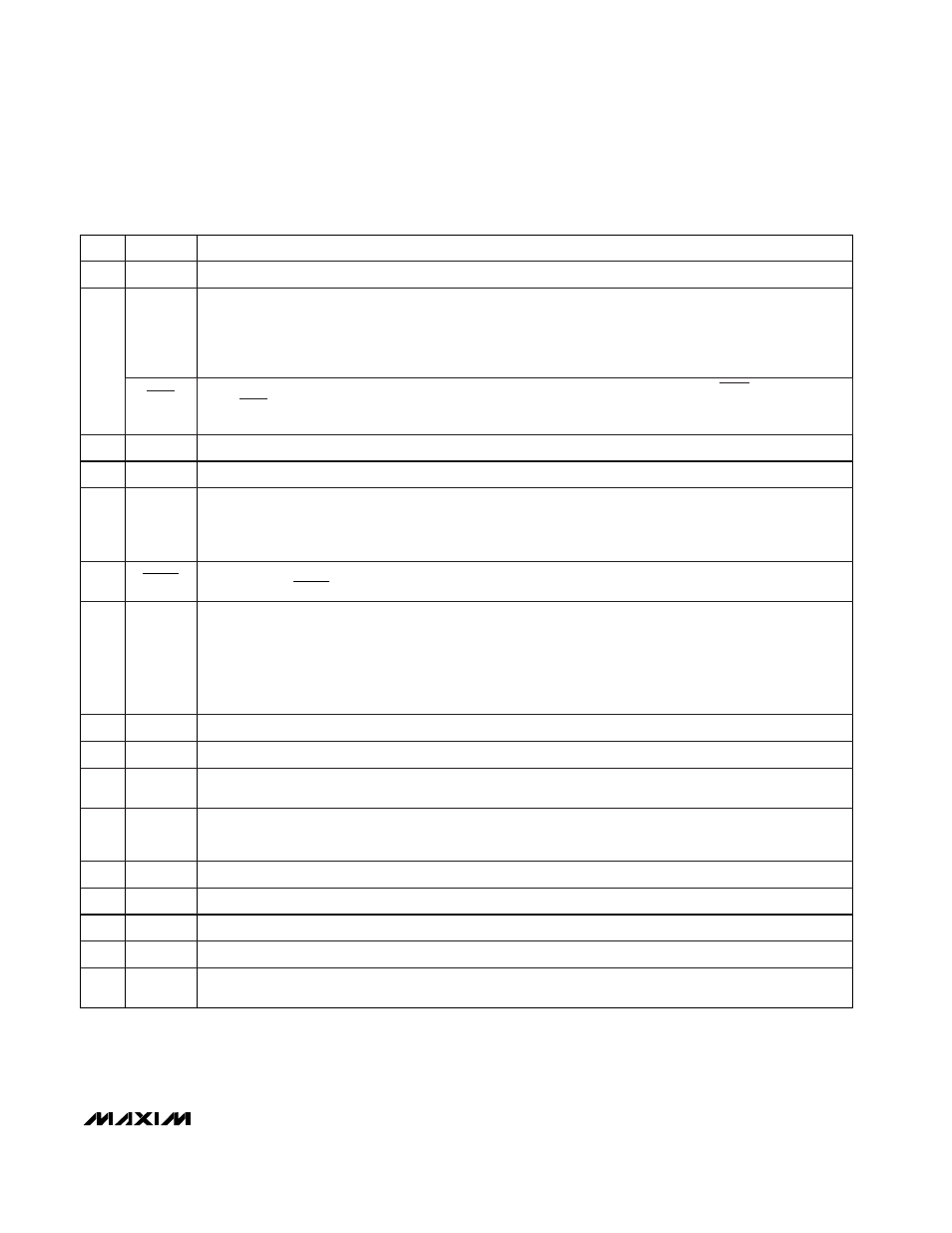
______________________________________________________________Pin Description
Current-Sense input, High side. Current-limit level is 100mV referred to CSL.
CSH
8
Current-Sense input, Low side. Also serves as the feedback input in fixed-output modes.
CSL
9
Battery voltage input (4.5V to 30V). Bypass V+ to PGND close to the IC with a 0.1µF capacitor. Connects to a
linear regulator that powers VL.
V+
10
5V Internal linear-regulator output. VL is also the supply voltage rail for the chip. VL is switched to the output
voltage via CSL (V
CSL
> 4.5V) for automatic bootstrapping. Bypass to GND with 4.7µF. VL can
supply up to 5mA for external loads.
VL
11
Power Ground.
PGND
12
Low-noise analog Ground and feedback reference point.
GND
4
Oscillator Synchronization and frequency select. Tie to GND or VL for 150kHz operation; tie to REF for
300kHz operation. A high-to-low transition begins a new cycle. Drive SYNC with 0V to 5V logic levels (see the
Electrical Characteristics
table for V
IH
and V
IL
specifications). SYNC capture range is 190kHz to 340kHz
guaranteed.
SYNC
5
Shutdown control input, active low. Logic threshold is set at approximately 1V (V
TH
of an internal N-channel
MOSFET). Tie SHDN to V+ for automatic start-up.
SHDN
6
Feedback input. Regulates at FB = REF (approximately 2.505V) in adjustable mode. FB is a Dual-Mode
TM
input that also selects the fixed output voltage settings as follows:
•
Connect to GND for 3.3V operation.
•
Connect to VL for 5V operation.
•
Connect FB to a resistor divider for adjustable mode. FB can be driven with +5V rail-to-rail logic in order to
change the output voltage under system control.
FB
7
Reference voltage output. Bypass to GND with 0.33µF minimum.
REF
3
PIN
Secondary winding Feedback input. Normally connected to a resistor divider from an auxiliary output.
Don’t leave SECFB unconnected.
•
MAX796: SECFB regulates at VSECFB = 2.505V. Tie to VL if not used.
•
MAX799: SECFB regulates at VSECFB = 0V. Tie to a negative voltage through a high-value current-limit-
ing resistor (I
MAX
= 100µA) if not used.
SECFB
(MAX796/
MAX799)
2
Soft-Start timing capacitor connection. Ramp time to full current limit is approximately 1ms/nF.
SS
1
FUNCTION
NAME
Low-side gate-drive output. Normally drives the synchronous-rectifier MOSFET. Swings 0V to VL.
DL
13
Boost capacitor connection for high-side gate drive (0.1µF).
BST
14
Switching node (inductor) connection. Can swing 2V below ground without hazard.
LX
15
High-side gate-drive output. Normally drives the main buck switch. DH is a floating driver output that swings
from LX to BST, riding on the LX switching-node voltage.
DH
16
Dual Mode is a trademark of Maxim Integrated Products.
Disables pulse-skipping mode when high. Connect to GND for normal use.
Don’t leave SKIP unconnected.
With SKIP grounded, the device will
automatically
change from pulse-skipping operation to full PWM opera-
tion when the load current exceeds approximately 30% of maximum. (See Table 3.)
SKIP
(MAX797)