Low-voltage operation, Applications information, Table 4. low-voltage troubleshooting – Rainbow Electronics MAX799 User Manual
Page 23
MAX796/MAX797/MAX799
Step-Down Controllers with
Synchronous Rectifier for CPU Power
______________________________________________________________________________________
23
____________Low-Voltage Operation
Low input voltages and low input-output differential volt-
ages each require some extra care in the design. Low
absolute input voltages can cause the VL linear regulator
to enter dropout, and eventually shut itself off. Low input
voltages relative to the output (low V
IN
-V
OUT
differential)
can cause bad load regulation in multi-output flyback
applications. See the design equations in the
Transformer
Design
section. Finally, low V
IN
-V
OUT
differentials can also
cause the output voltage to sag when the load current
changes abruptly. The amplitude of the sag is a function
of inductor value and maximum duty factor (an
Electrical
Characteristics
parameter, 93% guaranteed over temper-
ature at f = 150kHz) as follows:
(I
STEP
)
2
x L
V
SAG
= ———————————————
2 x C
F
x (V
IN(MIN)
x D
MAX
- V
OUT
)
The cure for low-voltage sag is to increase the value of
the output capacitor. For example, at V
IN
= 5.5V, V
OUT
= 5V, L = 10µH, f = 150kHz, a total capacitance of
660µF will prevent excessive sag. Note that only the
capacitance requirement is increased and the ESR
requirements don’t change. Therefore, the added
capacitance can be supplied by a low-cost bulk
capacitor in parallel with the normal low-ESR capacitor.
__________Applications Information
Heavy-Load Efficiency Considerations
The major efficiency loss mechanisms under loads are,
in the usual order of importance:
•
P(I
2
R), I
2
R losses
•
P(gate), gate-charge losses
•
P(diode), diode-conduction losses
•
P(tran), transition losses
•
P(cap), capacitor ESR losses
•
P(IC), losses due to the operating supply current
of the IC
Inductor-core losses are fairly low at heavy loads
because the inductor’s AC current component is small.
Therefore, they aren’t accounted for in this analysis.
Ferrite cores are preferred, especially at 300kHz, but
powdered cores such as Kool-mu can work well.
Efficiency = P
OUT
/ P
IN
x 100%
= P
OUT
/ (P
OUT
+ P
TOTAL
) x 100%
P
TOTAL
= P(I
2
R) + P(gate) + P(diode) + P(tran) +
P(cap) + P(IC)
P(I
2
R) = (I
LOAD
)
2
x (R
DC
+ R
DS(ON)
+ R
SENSE
)
where R
DC
is the DC resistance of the coil, R
DS(ON)
is
the MOSFET on-resistance, and R
SENSE
is the current-
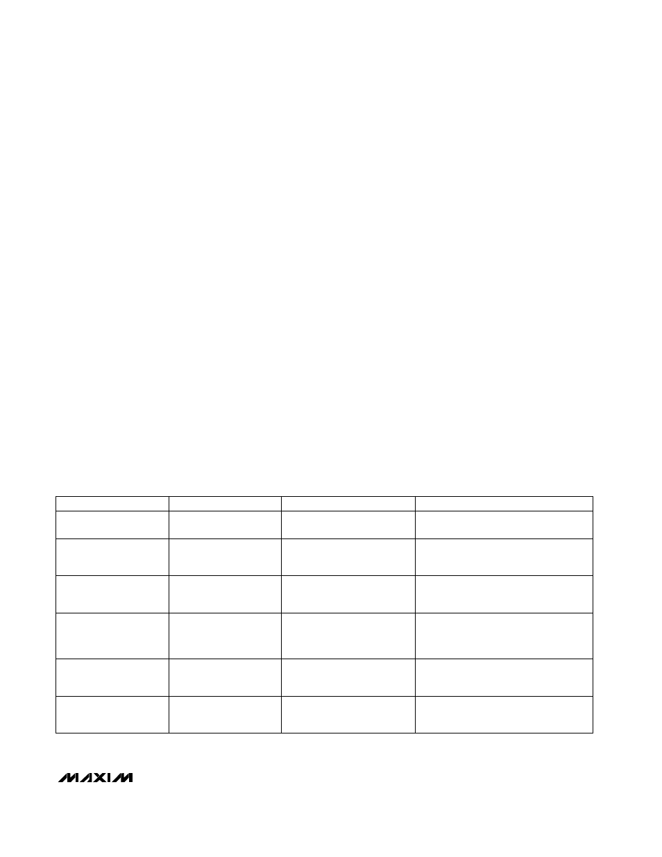
Table 4. Low-Voltage Troubleshooting
Supply VL from an external source other
than V
BATT
, such as the system 5V supply.
VL output is so low that it hits the
VL UVLO threshold at 4.2V max.
Low input voltage, <4.5V
Won’t start under load or
quits before battery is
completely dead
Use a small 20mA Schottky diode for
boost diode D2. Supply VL from an
external source.
VL linear regulator is going into
dropout and isn’t providing
good gate-drive levels.
Low input voltage, <5V
High supply current,
poor efficiency
Reduce f to 150kHz. Reduce secondary
impedances—use Schottky if possible.
Stack secondary winding on main output.
Not enough duty cycle left to
initiate forward-mode operation.
Small AC current in primary can’t
store energy for flyback operation.
Low V
IN
-V
OUT
differential,
V
IN
< 1.3 x V
OUT
(main)
(MAX796/MAX799 only)
Secondary output won’t
support a load
Reduce L value. Tolerate the remaining
jitter (extra output capacitance helps
somewhat).
Inherent limitation of fixed-fre-
quency current-mode SMPS
slope compensation.
Low V
IN
-V
OUT
differential,
<1V
Unstable—jitters between
two distinct duty factors
Reduce f to 150kHz. Reduce MOSFET
on-resistance and coil DCR.
Maximum duty-cycle limits
exceeded.
Low V
IN
-V
OUT
differential,
<1V
Dropout voltage is too
high (V
OUT
follows V
IN
as
V
IN
decreases)
Increase bulk output capacitance per
formula above. Reduce inductor value.
Limited inductor-current slew
rate per cycle.
Low V
IN
-V
OUT
differential,
<1.5V
Sag or droop in V
OUT
under step load change
SOLUTION
ROOT CAUSE
CONDITION
SYMPTOM