Soft-start circuit (ss), Shutdown – Rainbow Electronics MAX799 User Manual
Page 18
MAX796/MAX797/MAX799
Step-Down Controllers with
Synchronous Rectifier for CPU Power
18
______________________________________________________________________________________
MAX796), a 1µs one-shot is triggered that extends the
low-side switch’s on-time beyond the point where the
inductor current crosses zero (in discontinuous mode).
This causes the inductor (primary) current to reverse,
which in turn pulls current out of the output filter capacitor
and causes the flyback transformer to operate in the for-
ward mode. The low impedance presented by the trans-
former secondary in the forward mode dumps current into
the secondary output, charging up the secondary capac-
itor and bringing SECFB back into regulation. The SECFB
feedback loop does not improve secondary output accu-
racy in normal flyback mode, where the main (primary)
output is heavily loaded. In this mode, secondary output
accuracy is determined, as usual, by the secondary recti-
fier drop, turns ratio, and accuracy of the main output
voltage. So, a linear post-regulator may still be needed in
order to meet tight output accuracy specifications.
The secondary output voltage-regulation point is deter-
mined by an external resistor divider at SECFB. For nega-
tive output voltages, the SECFB comparator is referenced
to GND (MAX799); for positive output voltages, SECFB
regulates at the 2.505V reference (MAX796). As a result,
output resistor divider connections and design equations
for the two device types differ slightly (Figure 9).
Ordinarily, the secondary regulation point is set 5% to
10% below the voltage normally produced by the flyback
effect. For example, if the output voltage as determined
by the turns ratio is +15V, the feedback resistor ratio
should be set to produce about +13.5V; otherwise, the
SECFB one-shot might be triggered unintentionally, caus-
ing an unnecessary increase in supply current and output
noise. In negative-output (MAX799) applications, the
resistor divider acts as a load on the internal reference,
which in turn can cause errors at the main output. Avoid
overloading REF (see the Reference Load-Regulation
Error vs. Load Current graph in the
Typical Operating
Characteristics
). 100k
Ω
is a good value for R3 in MAX799
circuits.
Soft-Start Circuit (SS)
Soft-start allows a gradual increase of the internal cur-
rent-limit level at start-up for the purpose of reducing
input surge currents, and perhaps for power-supply
sequencing. In shutdown mode, the soft-start circuit
holds the SS capacitor discharged to ground. When
SHDN goes high, a 4µA current source charges the SS
capacitor up to 3.2V. The resulting linear ramp wave-
form causes the internal current-limit level to increase
proportionally from 20mV to 100mV. The main output
capacitor thus charges up relatively slowly, depending
on the SS capacitor value. The exact time of the output
rise depends on output capacitance and load current
and is typically 1ms per nanofarad of soft-start capaci-
tance. With no SS capacitor connected, maximum cur-
rent limit is reached within 10µs.
Shutdown
Shutdown mode (SHDN = 0V) reduces the V+ supply
current to typically 1µA. In this mode, the reference and
VL are inactive. SHDN is a logic-level input, but it can
be safely driven to the full V+ range. Connect SHDN to
V+ for automatic start-up. Do not allow slow transitions
(slower than 0.02V/µs) on SHDN.
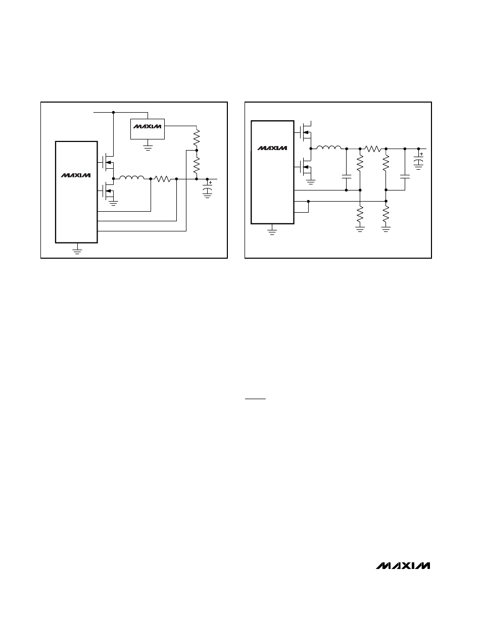
MAX796
MAX797
MAX799
MAX874
CSL
CSH
GND
FB
R5
VREF2 >>VREF
(4.096V)
R4
MAIN
OUTPUT
DH
DL
V
OUT
= V
REF
- (V
REF2
- V
REF
) (–––)
R4
R5
V+
Figure 7. Output Voltage Less than 2.5V
MAX796
MAX797
MAX799
CSL
CSH
0.01
µ
F
0.01
µ
F
GND
FB
OUTPUT
(8V AS
SHOWN)
DH
DL
V
OUT
R
SENSE
DIVIDER IMPEDANCE
≤
5k
Ω
(EACH LEG)
= V
REF
(1 + –––)
R3
R4
V+
R1
2.43k
R2
1.1k
R3
2.43k
R4
1.1k
Figure 8. Adjusting the Output Voltage to Greater than 6V