1 conversion sequence, 2 power-on-default states, 3 smbus interface – Rainbow Electronics LM95221 User Manual
Page 8: 4 temperature data format, Bit, 2's complement (10-bit plus sign), Bit, unsigned binary, 0 functional description
1.0 Functional Description
(Continued)
7.
Status Register: busy, diode fault
8.
Configuration Register: resolution control, conversion
rate control, standby control
9.
1-shot Register
10. Manufacturer ID
11. Revision ID
1.1 CONVERSION SEQUENCE
The LM95221 takes approximately 66 ms to convert the
Local Temperature, Remote Temperature 1 and 2, and to
update all of its registers. Only during the conversion pro-
cess the busy bit (D7) in the Status register (02h) is high.
These conversions are addressed in a round robin se-
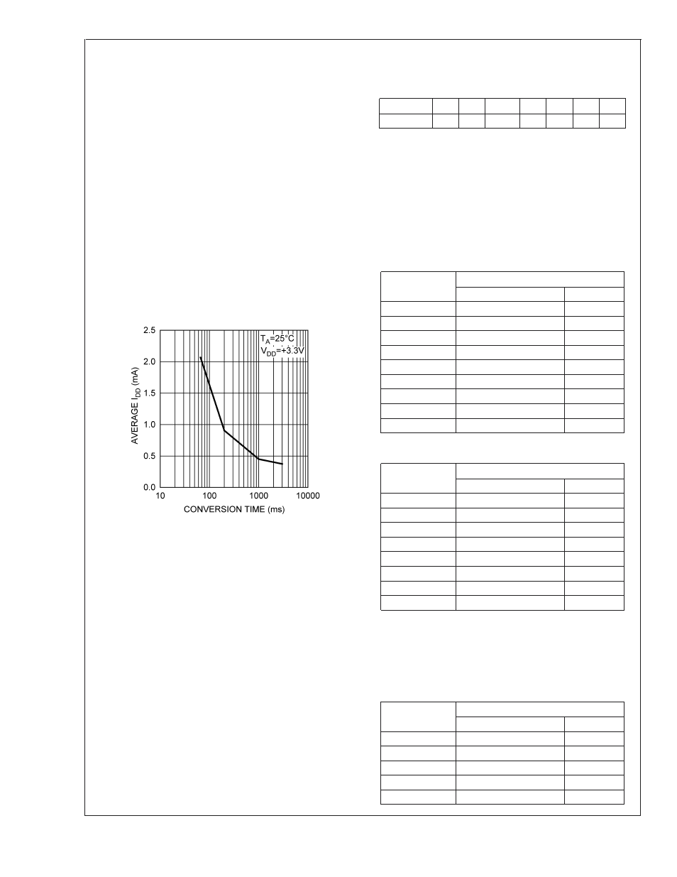
quence. The conversion rate may be modified by the Con-
version Rate bits found in the Configuration Register (03h).
When the conversion rate is modified a delay is inserted
between conversions, the actual conversion time remains at
66ms (26 ms for each remote and 14 ms for local). Different
conversion rates will cause the LM95221 to draw different
amounts of supply current as shown in Figure 2.
1.2 POWER-ON-DEFAULT STATES
LM95221 always powers up to these known default states.
The LM95221 remains in these states until after the first
conversion.
1.
Command Register set to 00h
2.
Local Temperature set to 0˚C
3.
Remote Diode Temperature set to 0˚C until the end of
the first conversion
4.
Status Register depends on state of thermal diode in-
puts
5.
Configuration register set to 00h; continuous conversion,
time = 66ms
1.3 SMBus INTERFACE
The LM95221 operates as a slave on the SMBus, so the
SMBCLK line is an input and the SMBDAT line is bidirec-
tional. The LM95221 never drives the SMBCLK line and it
does not support clock stretching. According to SMBus
specifications, the LM95221 has a 7-bit slave address. All
bits A6 through A0 are internally programmed and can not be
changed by software or hardware. The LM95221 has the
following SMBus slave address:
Version
A6
A5
A4
A3
A2
A1
A0
LM95221
0
1
0
1
0
1
1
1.4 TEMPERATURE DATA FORMAT
Temperature data can only be read from the Local and
Remote Temperature registers .
Remote temperature data is represented by an 11-bit, two’s
complement word or unsigned binary word with an LSb
(Least Significant Bit) equal to 0.125˚C. The data format is a
left justified 16-bit word available in two 8-bit registers. Un-
used bits will always report "0".
11-bit, 2’s complement (10-bit plus sign)
Temperature
Digital Output
Binary
Hex
+125˚C
0111 1101 0000 0000
7D00h
+25˚C
0001 1001 0000 0000
1900h
+1˚C
0000 0001 0000 0000
0100h
+0.125˚C
0000 0000 0010 0000
0020h
0˚C
0000 0000 0000 0000
0000h
−0.125˚C
1111 1111 1110 0000
FFE0h
−1˚C
1111 1111 0000 0000
FF00h
−25˚C
1110 0111 0000 0000
E700h
−55˚C
1100 1001 0000 0000
C900h
11-bit, unsigned binary
Temperature
Digital Output
Binary
Hex
+255.875˚C
1111 1111 1110 0000
FFE0h
+255˚C
1111 1111 0000 0000
FF00h
+201˚C
1100 1001 0000 0000
C900h
+125˚C
0111 1101 0000 0000
7D00h
+25˚C
0001 1001 0000 0000
1900h
+1˚C
0000 0001 0000 0000
0100h
+0.125˚C
0000 0000 0010 0000
0020h
0˚C
0000 0000 0000 0000
0000h
Local Temperature data is represented by a 10-bit, two’s
complement word with an LSb (Least Significant Bit) equal to
0.25˚C. The data format is a left justified 16-bit word avail-
able in two 8-bit registers. Unused bits will always report "0".
Local temperature readings greater than +127.875˚C are not
clamped to +127.875˚C, they will roll-over to negative tem-
perature readings.
Temperature
Digital Output
Binary
Hex
+125˚C
0111 1101 0000 0000
7D00h
+25˚C
0001 1001 0000 0000
1900h
+1˚C
0000 0001 0000 0000
0100h
+0.125˚C
0000 0000 0010 0000
0020h
0˚C
0000 0000 0000 0000
0000h
20094306
FIGURE 2. Conversion Rate Effect on Power Supply
Current
LM95221
www.national.com
8