0 applications hints, 1 diode non-ideality, 1 diode non-ideality factor effect on accuracy – Rainbow Electronics LM95221 User Manual
Page 14
3.0 Applications Hints
The LM95221 can be applied easily in the same way as
other integrated-circuit temperature sensors, and its remote
diode sensing capability allows it to be used in new ways as
well. It can be soldered to a printed circuit board, and be-
cause the path of best thermal conductivity is between the
die and the pins, its temperature will effectively be that of the
printed circuit board lands and traces soldered to the
LM95221’s pins. This presumes that the ambient air tem-
perature is almost the same as the surface temperature of
the printed circuit board; if the air temperature is much higher
or lower than the surface temperature, the actual tempera-
ture of the LM95221 die will be at an intermediate tempera-
ture between the surface and air temperatures. Again, the
primary thermal conduction path is through the leads, so the
circuit board temperature will contribute to the die tempera-
ture much more strongly than will the air temperature.
To measure temperature external to the LM95221’s die, use
a remote diode. This diode can be located on the die of a
target IC, allowing measurement of the IC’s temperature,
independent of the LM95221’s temperature. The LM95221
has been optimized to measure the remote thermal diode
with a non-ideality of 1.008 and a series resistance of 2.7
Ω.
The thermal diode on the Pentium 4 processor on the 90 nm
process has a typical non-ideality of 1.011 and a typical
series resistance of 3.33
Ω. Therefore, when measuring this
thermal diode with the LM95221 a typical offset of +1.5˚C will
be observed. This offset can be compensated for easily by
subracting 1.5˚C from the LM95221’s readings. A discrete
diode can also be used to sense the temperature of external
objects or ambient air. Remember that a discrete diode’s
temperature will be affected, and often dominated, by the
temperature of its leads.
Most silicon diodes do not lend themselves well to this
application. It is recommended that a 2N3904 transistor
base emitter junction be used with the collector tied to the
base.
When measuring a diode-connected 2N3904, with an
LM95221, an offset of -3.25˚C will be observed. This offset
can simply be added to the LM95221’s reading: T
2N3904
=
T
LM95221
+ 3.25˚C
3.1 DIODE NON-IDEALITY
3.1.1 Diode Non-Ideality Factor Effect on Accuracy
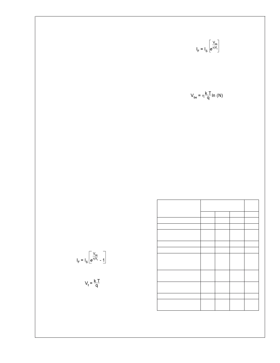
When a transistor is connected as a diode, the following
relationship holds for variables V
BE
, T and I
f
:
where:
•
q = 1.6x10
−19
Coulombs (the electron charge),
•
T = Absolute Temperature in Kelvin
•
k = 1.38x10
−23
joules/K (Boltzmann’s constant),
•
η is the non-ideality factor of the process the diode is
manufactured on,
•
I
S
= Saturation Current and is process dependent,
•
I
f
= Forward Current through the base emitter junction
•
V
BE
= Base Emitter Voltage drop
In the active region, the -1 term is negligible and may be
eliminated, yielding the following equation
In the above equation,
η and I
S
are dependant upon the
process that was used in the fabrication of the particular
diode. By forcing two currents with a very controlled ratio (N)
and measuring the resulting voltage difference, it is possible
to eliminate the I
S
term. Solving for the forward voltage
difference yields the relationship:
The voltage seen by the LM95221 also includes the I
F
R
S
voltage drop of the series resistance. The non-ideality factor,
η, is the only other parameter not accounted for and de-
pends on the diode that is used for measurement. Since
∆V
BE
is proportional to both
η and T, the variations in η
cannot be distinguished from variations in temperature.
Since the non-ideality factor is not controlled by the tempera-
ture sensor, it will directly add to the inaccuracy of the
sensor. For the Pentium 4 and Mobile Pentium Processor-M
Intel specifies a
±
0.1% variation in
η from part to part. As an
example, assume a temperature sensor has an accuracy
specification of
±
1˚C at room temperature of 25 ˚C and the
process used to manufacture the diode has a non-ideality
variation of
±
0.1%. The resulting accuracy of the tempera-
ture sensor at room temperature will be:
T
ACC
=
±
1˚C + (
±
0.1% of 298 ˚K) =
±
1.4 ˚C
The additional inaccuracy in the temperature measurement
caused by
η, can be eliminated if each temperature sensor is
calibrated with the remote diode that it will be paired with.
Processor Family
η, non-ideality
Series
R
min
typ
max
Pentium II
1
1.0065 1.0173
Pentium III CPUID 67h
1
1.0065 1.0125
Pentium III CPUID
68h/PGA370Socket/Celeron
1.0057
1.008
1.0125
Pentium 4, 423 pin
0.9933 1.0045 1.0368
Pentium 4, 478 pin
0.9933 1.0045 1.0368
Pentium 4 on 0.13
micron process,
2-3.06GHz
1.0011 1.0021 1.0030 3.64
Ω
Pentium 4 on 90 nm
process
1.011
3.33
Ω
Pentium M Processor
(Centrino)
1.00151 1.00220 1.00289 3.06
Ω
MMBT3904
1.003
AMD Athlon MP model
6
1.002
1.008
1.016
LM95221
www.national.com
14