Connection diagram, Ordering information, Pin descriptions – Rainbow Electronics LM95221 User Manual
Page 2
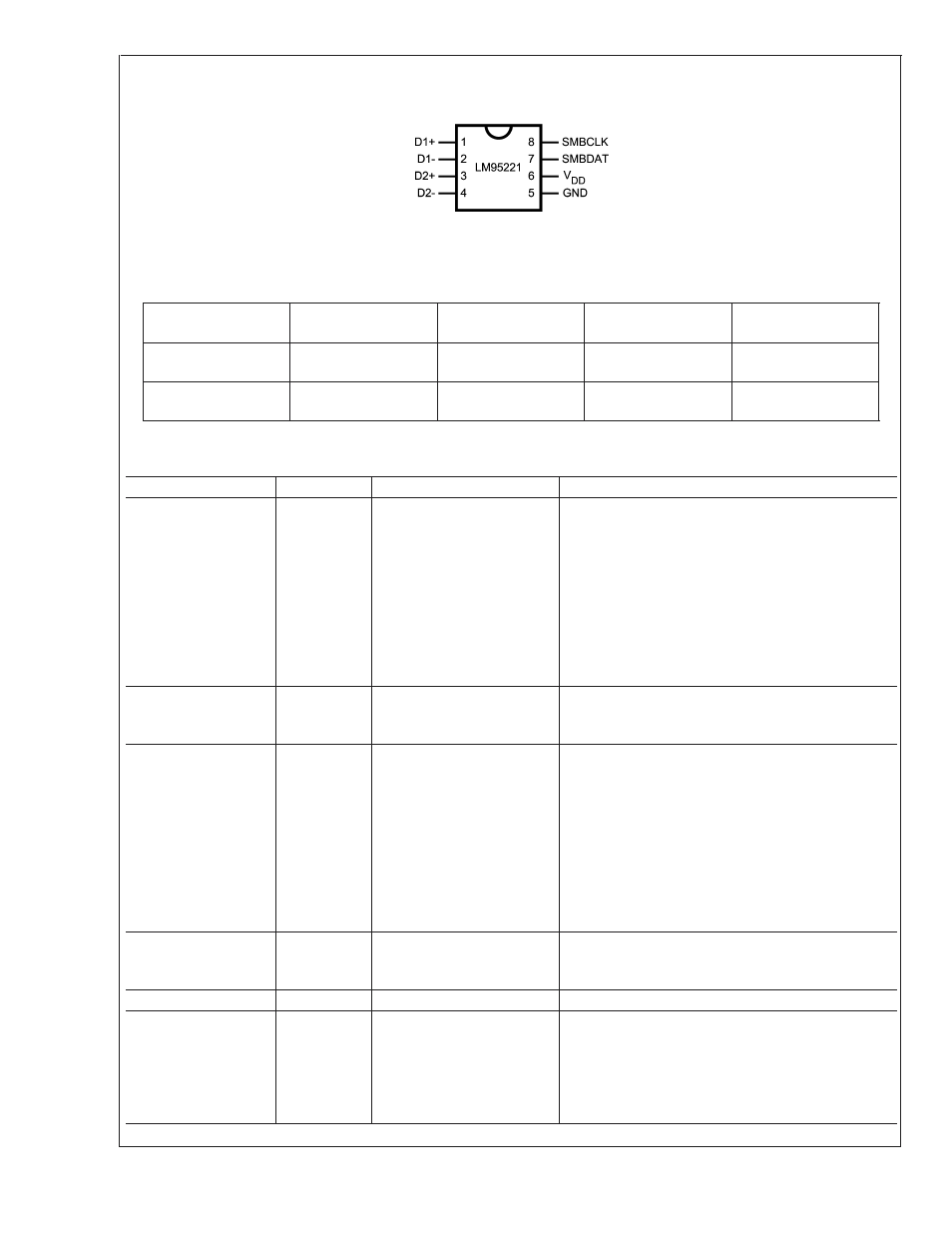
Connection Diagram
MSOP-8
20094302
TOP VIEW
Ordering Information
Part Number
Package
Marking
NS Package
Number
Transport
Media
SMBus Device
Address
LM95221CIMM
LM95221CIMM
MUA08A (MSOP-8)
1000 Units on Tape
and Reel
010 1011
LM95221CIMMX
LM95221CIMM
MUA08A (MSOP-8)
3500 Units on Tape
and Reel
010 1011
Pin Descriptions
Label
Pin #
Function
Typical Connection
D1+
1
Diode Current Source
To Diode Anode. Connected to remote discrete
diode-connected transistor junction or to the
diode-connected transistor junction on a remote IC
whose die temperature is being sensed. A 2.2 nF
diode bypass capacitor is recommended to filter high
frequency noise. Place the 2.2 nF capacitor between
and as close as possible to the LM95221’s D+ and
D− pins. Make sure the traces to the 2.2 nF
capacitor are matched. Ground this pin if this
thermal diode is not used.
D1−
2
Diode Return Current Sink
To Diode Cathode. A 2.2 nF capacitor is
recommended between D1+ and D1-. Ground this
pin if this thermal diode is not used.
D2+
3
Diode Current Source
To Diode Anode. Connected to remote discrete
diode-connected transistor junction or to the
diode-connected transistor junction on a remote IC
whose die temperature is being sensed. A 2.2 nF
diode bypass capacitor is recommended to filter high
frequency noise. Place the 2.2 nF capacitor between
and as close as possible to the LM95221’s D+ and
D− pins. Make sure the traces to the 2.2 nF
capacitor are matched. Ground this pin if this
thermal diode is not used.
D2−
4
Diode Return Current Sink
To Diode Cathode. A 2.2 nF capacitor is
recommended between D2+ and D2-. Ground this
pin if this thermal diode is not used.
GND
5
Power Supply Ground
Ground
V
DD
6
Positive Supply Voltage
Input
DC Voltage from 3.0 V to 3.6 V. V
DD
should be
bypassed with a 0.1 µF capacitor in parallel with 100
pF. The 100 pF capacitor should be placed as close
as possible to the power supply pin. Noise should
be kept below 200 mVp-p, a 10 µF capacitor may be
required to achieve this.
LM95221
www.national.com
2