Logic electrical characteristics – Rainbow Electronics LM95221 User Manual
Page 5
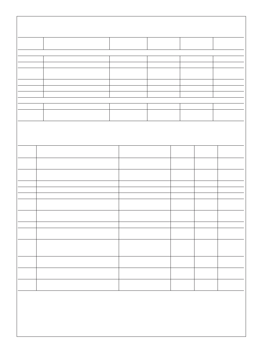
Logic Electrical Characteristics
DIGITAL DC CHARACTERISTICS Unless otherwise noted, these specifications apply for V
DD
=+3.0 to 3.6 Vdc. Boldface lim-
its apply for T
A
= T
J
= T
MIN
to T
MAX
; all other limits T
A
= T
J
=+25˚C, unless otherwise noted.
Symbol
Parameter
Conditions
Typical
Limits
Units
(Limit)
SMBDAT, SMBCLK INPUTS
V
IN(1)
Logical “1” Input Voltage
2.1
V (min)
V
IN(0)
Logical “0”Input Voltage
0.8
V (max)
V
IN(HYST)
SMBDAT and SMBCLK Digital Input
Hysteresis
400
mV
I
IN(1)
Logical “1” Input Current
V
IN
= V
DD
0.005
±
10
µA (max)
I
IN(0)
Logical “0” Input Current
V
IN
= 0 V
−0.005
±
10
µA (max)
C
IN
Input Capacitance
5
pF
SMBDAT OUTPUT
I
OH
High Level Output Current
V
OH
= V
DD
10
µA (max)
V
OL
SMBus Low Level Output Voltage
I
OL
= 4mA
I
OL
= 6mA
0.4
0.6
V (max)
SMBus DIGITAL SWITCHING CHARACTERISTICS Unless otherwise noted, these specifications apply for V
DD
=+3.0 Vdc to
+3.6 Vdc, C
L
(load capacitance) on output lines = 80 pF. Boldface limits apply for T
A
= T
J
= T
MIN
to T
MAX
; all other limits T
A
= T
J
= +25˚C, unless otherwise noted. The switching characteristics of the LM95221 fully meet or exceed the published specifi-
cations of the SMBus version 2.0. The following parameters are the timing relationships between SMBCLK and SMBDAT sig-
nals related to the LM95221. They adhere to but are not necessarily the SMBus bus specifications.
Symbol
Parameter
Conditions
Typical
Limits
Units
(Limit)
f
SMB
SMBus Clock Frequency
100
10
kHz (max)
kHz (min)
t
LOW
SMBus Clock Low Time
from V
IN(0)
max to V
IN(0)
max
4.7
25
µs (min)
ms (max)
t
HIGH
SMBus Clock High Time
from V
IN(1)
min to V
IN(1)
min
4.0
µs (min)
t
R,SMB
SMBus Rise Time
1
µs (max)
t
F,SMB
SMBus Fall Time
0.3
µs (max)
t
OF
Output Fall Time
C
L
= 400pF,
I
O
= 3mA, (Note 13)
250
ns (max)
t
TIMEOUT
SMBDAT and SMBCLK Time Low for Reset of
Serial Interface (Note 14)
25
35
ms (min)
ms (max)
t
SU;DAT
Data In Setup Time to SMBCLK High
250
ns (min)
t
HD;DAT
Data Out Stable after SMBCLK Low
300
900
ns (min)
ns (max)
t
HD;STA
Start Condition SMBDAT Low to SMBCLK
Low (Start condition hold before the first clock
falling edge)
100
ns (min)
t
SU;STO
Stop Condition SMBCLK High to SMBDAT
Low (Stop Condition Setup)
100
ns (min)
t
SU;STA
SMBus Repeated Start-Condition Setup Time,
SMBCLK High to SMBDAT Low
0.6
µs (min)
t
BUF
SMBus Free Time Between Stop and Start
Conditions
1.3
µs (min)
LM95221
www.national.com
5