Rainbow Electronics MAX1688 User Manual
Page 7
MAX1687/MAX1688
Step-Up DC-DC Converters with
Precise, Adaptive Current Limit for GSM
_______________________________________________________________________________________
7
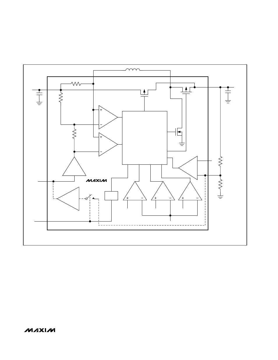
When starting up, the MAX1687/MAX1688 employ four
successive phases of operation to reduce the inrush of
current from the battery. These phases are Linear
Regulator Mode, Pseudo Buck Mode, Pseudo Boost
Mode, and Boost Mode. In Linear Mode, the output
connects to the input through a 30
Ω
precharge PMOS
device (Figure1, Q1). The transition from Linear Mode
to Pseudo Buck Mode occurs when V
OUT
= V
IN
- 3V.
The transition from Pseudo Buck Mode to Pseudo
Boost Mode occurs when V
OUT
= V
IN
- 0.7V. The tran-
sition from Pseudo Boost Mode to Boost Mode occurs
when V
OUT
> V
IN
. Due to these mode changes, the
battery input current remains relatively constant, and
V
OUT
changes slope as it rises.
Hysteretic Inductor-Current Control
Logic circuits in the MAX1687/MAX1688 control the
inductor ripple current to typically 200mA (Figure 2).
The voltage at LIM (CHG) programs I
PEAK
. The induc-
tor current oscillates between I
PEAK
- 200mA and
I
PEAK
.
Standby/Shutdown
When ON goes low, the device enters Standby Mode,
inductor current ramps to zero, and the output discon-
nects from the input. If ON remains low for greater than
1.2ms (typ), the device shuts down and quiescent cur-
rent drops to 3µA (typ).
Q3
REF
FB
V
OUT
V
OUT
V
PRECHARGE
V
IN
g
m
ON
( ) ARE FOR MAX1687
[ ] ARE FOR MAX1688 (ALSO DASHED LINES)
(LIM)
[CHG]
g
m
V
IN
-
V
DIODE
CONSTANT
HYSTERETIC
INDUCTOR-CURRENT
CONTROL LOGIC
PEAK/
TROUGH
INDUCTOR-
CURRENT
DETECT
Q2
P-SWITCH
N-SWITCH
ZERO
CROSSING
P-SWITCH
LX2
Q1
LX1
V
IN
MAX1687
MAX1688
TIMER
Figure 1. Functional Diagram