Electrical characteristics (continued) – Rainbow Electronics MAX783 User Manual
Page 3
MAX783
Triple-Output Power-Supply Controller
for Notebook Computers
_______________________________________________________________________________________
3
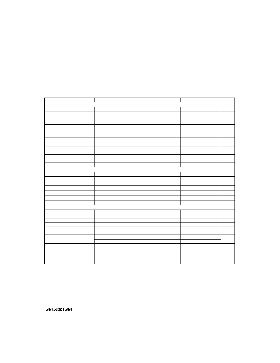
PARAMETER
Quiescent Power Consumption
(both controllers on)
MIN
TYP
MAX
5.2
8.6
UNITS
mW
Input Current
Off V+ Current
±1
µA
REF Fault Lockout Voltage
30
60
S
—
H
—
D
—
N
–
, ON3, ON5, DA0, DA1, DB0, DB1, V
IN
= 0V or 5V
2.4
3.2
V
REF Output Voltage
3.24
3.36
µA
V
VL - 0.5
4.2
4.7
V
V
SYNC
Input High Voltage
2.4
REF Load Regulation
30
75
mV
S
—
H
—
D
—
N
–
, ON3, ON5, DA0, DA1, DB0, DB1
D1, D2 Trip Voltage
Shutdown V+ Current
Input Low Voltage
0.8
25
40
1.61
1.69
µA
Standby V+ Current
V
V
70
110
µA
D1, D2 Input Current
S
—
H
—
D
—
N
–
, ON3, ON5, DA0, DA1, DB0, DB1, SYNC
±100
nA
Q1, Q2 R
—
D
—
Y
—
5
–
Source Current
VL Output Voltage
12
20
30
µA
Q1, Q2 R
—
D
—
Y
—
5
–
Sink Current
92
95
200
500
1000
%
µA
Q1, Q2, R
—
D
—
Y
—
5
–
Output High Voltage
SYNC = 0V or 5V
VH - 0.5
V
Q1, Q2, R
—
D
—
Y
—
5
–
Output Low Voltage
Maximum Duty Cycle
4.5
5.5
V
89
92
0.4
V
Quiescent VH Current
VL Fault Lockout Voltage
4
10
µA
SYNC = 3.3V
3.6
4.2
V
Oscillator SYNC Range
Oscillator Frequency
240
350
270
300
330
kHz
170
200
230
kHz
CONDITIONS
D1 = D2 = D3 = DA0 = DA1 = DB0 = DB1 = 0V,
FB5 = CS5 = 5.25V, FB3 = CS3 = 3.5V
FB5 = CS5 = 5.25V, VL switched over to FB5
Falling edge
No external load (Note 2)
Rising edge of FB5, hysteresis = 1%
SYNC Rise/Fall Time
0mA < I
L
< 5mA (Note 3)
Falling edge, hysteresis = 1%
–
S
—
H
—
D
—
N
–
= D1 = D2 = ON3 = ON5 = DA0 = DA1 = DB0 =
DB1 = 0V, V+ = 30V
D1 = D2 = ON3 = ON5 = DA0 = DA1 = DB0 = DB1 = 0V,
V+ = 30V
D1 = D2 = 0V to 5V
VH = 15V, V
OUT
= 2.5V
VH = 15V, V
OUT
2.5V
I
SOURCE
= 5µA, VH = 3V
ON5 = ON3 = 0V, 5.5V < V+ < 30V, 0mA < I
L
< 25mA
I
SINK
= 20µA, VH = 3V
VH = 18V, D1 = D2 = 5V, no external load
Falling edge, hysteresis = 1%
SYNC = 3.3V
SYNC = 0V or 5V
200
ns
Not tested
SYNC Low Pulse Width
200
ns
SYNC High Pulse Width
200
ns
ELECTRICAL CHARACTERISTICS (continued)
(V+ = 15V, GND = PGND = 0V, I
VL
= I
REF
= 0mA, S
—
H
—
D
—
N
–
= ON3 = ON5 = 5V, other digital input levels are 0V or +5V,
T
A
= T
MIN
to T
MAX
, unless otherwise noted.)
VL/FB5 Switchover Voltage
(also R
—
D
—
Y
—
5
–
Trip Voltage)
INTERNAL REGULATOR AND REFERENCE
COMPARATORS
OSCILLATOR AND INPUTS/OUTPUTS