Rainbow Electronics MAX3345E User Manual
Page 7
Power-Supply Configurations
Normal Operating Mode
Connect V
L
and V
CC
to system power supplies (Table
1). Connect V
L
to a +1.65V to +3.6V supply. Connect
V
CC
to a +4.0V to +5.5V supply. Alternatively, the
MAX3344E/MAX3345E can derive power from a single
Li+ battery. Connect the battery to V
CC.
V
VTRM
remains
above +3.0V for V
CC
as low as +3.1V.
Additionally, the MAX3344E/MAX3345E can derive
power from a 3.3V ±10% voltage regulator. Connect V
CC
and VTRM to an external +3.3V voltage regulator.
Disable Mode
Connect V
CC
to a system power supply and leave V
L
unconnected or connect to GND. D+ and D- enter a tri-
state mode and V
CC
consumes less than 20µA of supply
current. D+ and D- withstand external signals up to
+5.5V in disable mode (Table 2).
Sharing Mode
Connect V
L
to a system power supply and leave V
CC
(or
V
CC
and VTRM) unconnected or connect to GND. D+
and D- enter a tri-state mode, allowing other circuitry to
share the USB D+ and D- lines, and V
L
consumes less
than 20µA of supply current. D+ and D- withstand exter-
nal signals up to +5.5V in sharing mode (Table 2).
Device Control
D+ and D-
D+ and D- are the USB-side transmitter I/O connec-
tions, and are ESD protected to ±15kV using the
Human Body Model, ±10kV using IEC 1000-4-2 Air-
Gap Discharge, and ±8kV using IEC 1000-4-2 Contact
Discharge, making the MAX3344E/MAX3345E ideal for
applications where a robust transmitter is required. A
23.7Ω resistor is required on D+ and D- for normal
operation (see the External Resistors section).
ENUM
USB specification 2.0 requires a 1.5kΩ pullup resistor
on D+ for full-speed (12Mbps) operation. Controlled by
enumerate (ENUM), the MAX3344E/MAX3345E provide
this internal 1.5kΩ resistor. Drive ENUM high to connect
the pullup resistor from D+ to VTRM. Drive ENUM low to
disconnect the pullup resistor from D+ to VTRM.
VPO/VMO, VPI/VMI, and
OE
The MAX3344E/MAX3345E system-side inputs are VPO
and VMO. Data comes into the MAX3344E/MAX3345E
through VPO and VMO. VPO and VMO operate either
differentially with VPO as the positive terminal and VMO
as the negative terminal, or single ended with VPO as
the data input (see the MODE section).
MAX3344E/MAX3345E
±15kV ESD-Protected USB Transceivers
in UCSP with USB Detect
_______________________________________________________________________________________
7
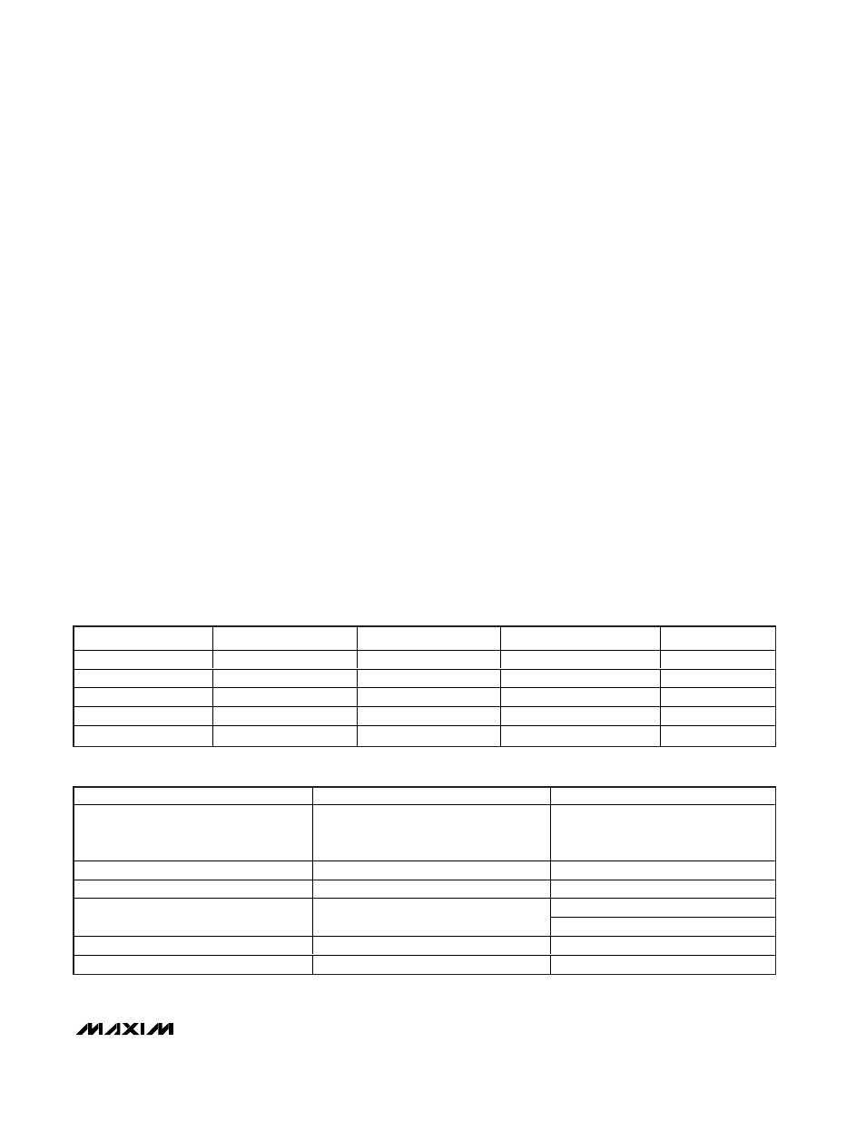
V
CC
(V)
VTRM (V)
V
L
(V)
CONFIGURATION
NOTES
+4.0 to +5.5
+3.3 Output
+1.65 to +3.6
Normal mode
—
+3.1 to +4.5
+3.3 Output
+1.65 to +3.6
Battery supply
—
+3.0 to +3.6
+3.0 to +3.6 Input
+1.65 to +3.6
Voltage regulator supply
—
GND or floating
Output
+1.65 to +3.6
Sharing mode
Table 2
+3.0 to +5.5
Output
GND or floating
Disable mode
Table 2
INPUTS/OUTPUTS
DISABLE MODE
SHARING MODE
V
CC
/VTRM
•
+5V input/+3.3V output
•
+3.3V input/+3.3V input
•
+3.7V input/+3.3V output
•
Floating or connected to GND
•
< +3.6V (MAX3344E)
•
< +1.0V (MAX3345E)
V
L
Floating or connected to GND
+1.65V to +3.6V input
D+ and D-
High impedance
High impedance
High impedance for
OE = Low
VPI and VMI
Invalid*
High for
OE = High
RCV
Invalid*
Undefined**
SPEED, SUSP,
OE, ENUM
High impedance
High impedance
Table 2. Disable-Mode and Sharing-Mode Configurations
Table 1. Power-Supply Configurations
*High Impedance or low.
**High or low.