Rainbow Electronics DS2502 User Manual
Page 3
DS2502
3 of 22
102199
follow the 1-Wire protocol detailed in the section “1-Wire Bus System.” The memory functions required
to read and program the EPROM sections of the DS2502 are not accessible until the ROM function
protocol has been satisfied. This protocol is described in the ROM functions flow chart (Figure 9). The 1-
Wire bus master must first provide one of four ROM function commands: 1) Read ROM, 2) Match ROM,
3) Search ROM, or 4) Skip ROM. After a ROM function sequence has been successfully executed, the
bus master may then provide any one of the memory function commands specific to the DS2502 (Figure
6).
The 1-Wire CRC of the lasered ROM is generated using the polynomial X
8
+ X
5
+ X
4
+ 1. Figure 4
shows a hardware implementation of this CRC generator. Additional information about the Dallas
Semiconductor 1-Wire Cyclic Redundancy Check is available in the Book of DS19xx iButton Standards.
The shift register acting as the CRC accumulator is initialized to 0. Then starting with the least significant
bit of the family code, 1 bit at a time is shifted in. After the 8th bit of the family code has been entered,
then the serial number is entered. After the 48
th
bit of the serial number has been entered, the shift
register contains the CRC value. Shifting in the 8 bits of CRC should return the shift register to all 0s.
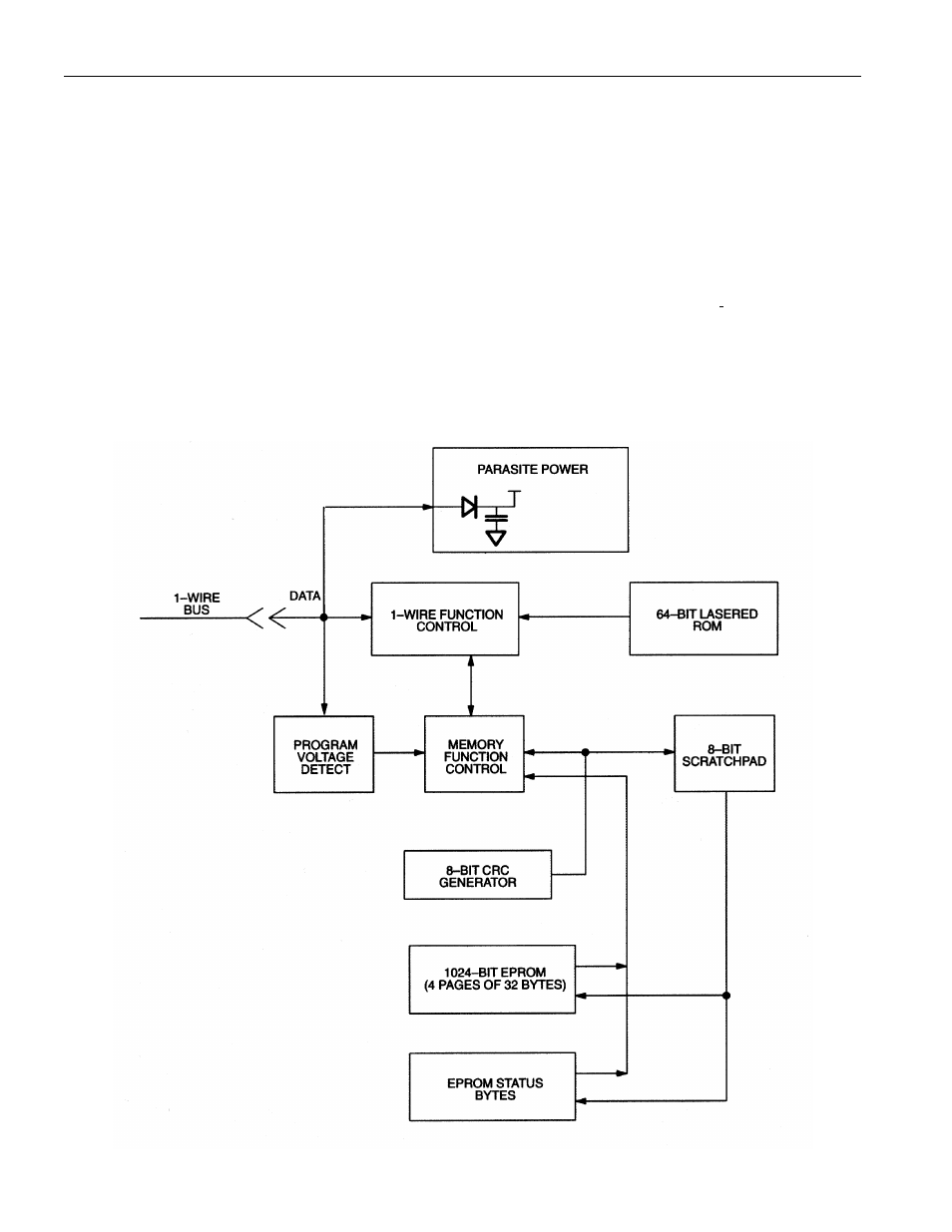
DS2502 BLOCK DIAGRAM Figure 1