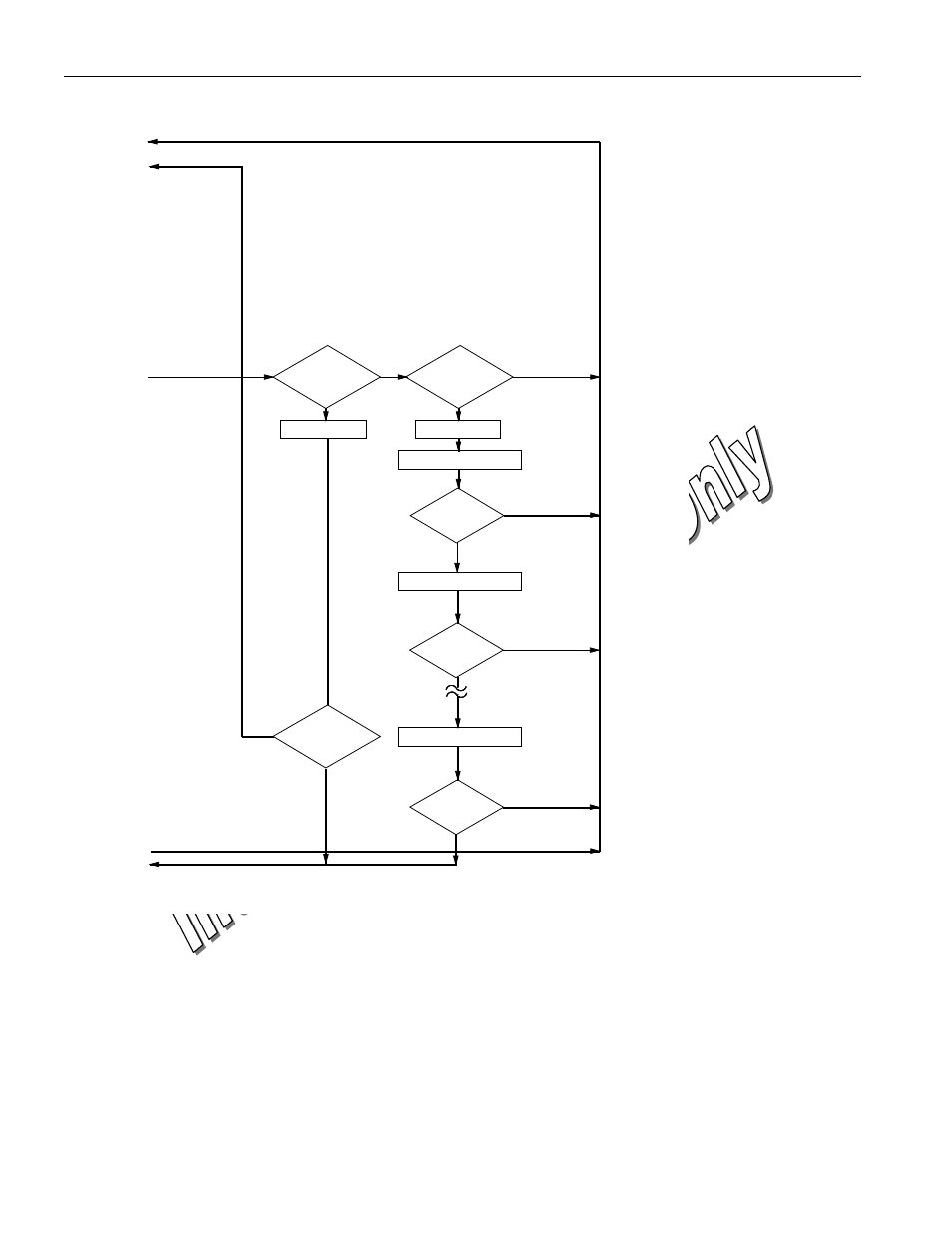
Rom functions flow chart figure 6 (cont’d) – Rainbow Electronics DS1957 User Manual
Page 19
DS1957
19 of 25
ROM FUNCTIONS FLOW CHART Figure 6 (cont’d)
N
Y
Y
3CH
OVERDRIVE
SKIP
?
69H
OVERDRIVE
MATCH
?
BIT 0
MATCH
?
BIT 1
MATCH
?
BIT 63
MATCH
?
N
N
N
Y
MASTER TX BIT 63
N
OD=1
OD=1
MASTER TX BIT 0
MASTER TX BIT 1
Y
3)
3)
3)
TO FIGURE 6 FIRST PART
FROM FIGURE 6
FIRST PART
FROM FIGURE 6
FIRST PART
TO FIGURE 6
FIRST PART
Y
3) ALWAYS TO BE TRANSMITTED AT OVERDRIVE SPEED
MASTER
TX RESET
PULSE
?
Y
N
The initialization sequence required to begin any communication with the DS1957 is shown in Figure 7.
A Reset Pulse followed by a Presence Pulse indicates the DS1957 is ready to accept a ROM command.
The bus master transmits (TX) a reset pulse (t
RSTL,
minimum 480 µs at regular speed, 48 µs at Overdrive
Speed). The bus master then releases the line and goes into receive mode (RX). The 1-Wire bus is pulled
to a high state via the pull-up resistor. After detecting the rising edge on the data pin, the DS1957 waits
(t
PDH
, 15-60 µs at regular speed, 2-6 µs at overdrive speed) and then transmits the presence pulse (t
PDL
,
60-240 µs at regular speed, 8-24 µs at Overdrive Speed).
A Reset Pulse of 480 µs or longer will exit the Overdrive Mode returning the device to regular speed. If
the DS1957 is in Overdrive Mode and the Reset Pulse is no longer than 80 µs the device will remain in
Overdrive Mode.