Pin description, Processor-controlled mode, Stand-alone mode – Rainbow Electronics DS1086L User Manual
Page 7
DS1086
DS1086 Spread-Spectrum EconOscillator
_____________________________________________________________________
7
Pin Description
PIN
NAME
FUNCTION
1
OUT
Oscillator Output
2
SPRD
Dither Enable. When the pin is high, the dither is enabled. When the pin is low, the dither is disabled.
3
V
CC
Power Supply
4
GND
Ground
5
OE
Output Enable. When the pin is high, the output buffer is enabled. When the pin is low, the output is
disabled but the master oscillator is still on.
6
PDN
Power-Down. When the pin is high, the master oscillator is enabled. When the pin is low, the master
oscillator is disabled (power-down mode).
7
SDA
2-Wire Serial Data. This pin is for serial data transfer to and from the device. The pin is open drain
and can be wire-OR’ed with other open-drain or open-collector interfaces.
8
SCL
2-Wire Serial Clock. This pin is used to clock data into the device on rising edges and clock data out
on falling edges.
DS1086
DITHERED 260kHz TO
133MHz OUTPUT
DECOUPLING CAPACITORS
(0.1
µF and 0.01µF)
SPRD
OUT
V
CC
V
CC
V
CC
4.7k
Ω
4.7k
Ω
V
CC
2-WIRE
INTERFACE
GND
SCL
SDA
PDN
OE
Processor-Controlled Mode
DS1086
XTL1/OSC1
MICRO-
PROCESSOR
XTL2/OSC2
DITHERED 260kHz TO
133MHz OUTPUT
DECOUPLING CAPACITORS
(0.1
µF and 0.01µF)
*SDA AND SCL CAN BE CONNECTED DIRECTLY HIGH IF THE DS1086 NEVER NEEDS
TO BE PROGRAMMED IN-CIRCUIT, INCLUDING DURING PRODUCTION TESTING.
SPRD
OUT
V
CC
V
CC
V
CC
GND
N.C.
SCL*
SDA*
PDN
OE
Stand-Alone Mode
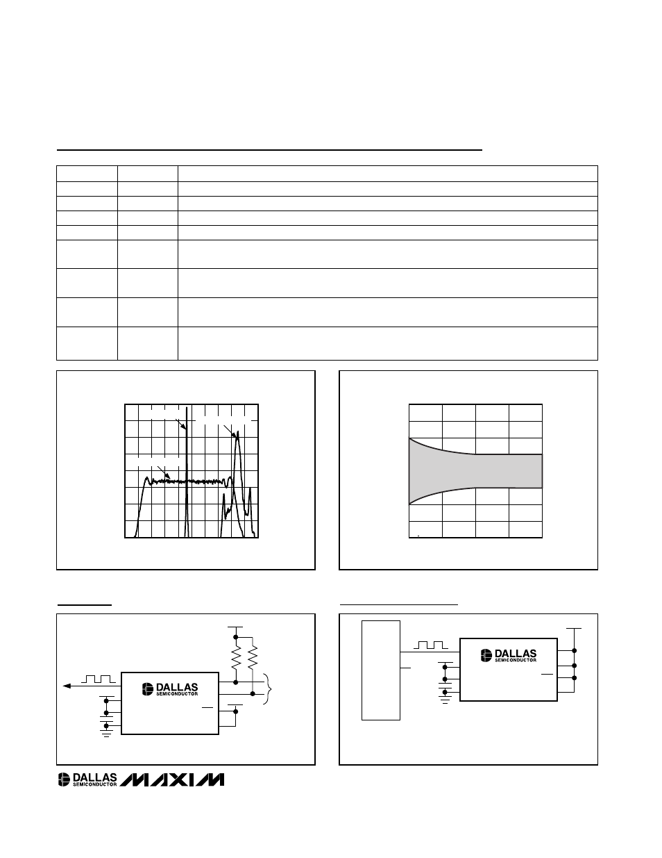
CLOCK SPECTRUM COMPARISON
(9kHz BW, PEAK DETECT)
DS1086 fig01
FREQUENCY (MHz)
RELATIVE AMPLITUDE (dBm)
94
91
93
92
-35
-30
-25
-20
-15
-10
-5
0
-40
90
95
DS1086 NO DITHER
DS1086 4% DITHER
CRYSTAL OSC
Figure 1. Clock Spectrum Dither Comparison
MAXIMUM TEMPERATURE VARIATION
vs. MASTER FREQUENCY
FREQUENCY (MHz)
FREQUENCY % CHANGE FROM 25
°C
82.75
116.25
99.50
-1.5
-1.0
-0.5
0
0.5
1.0
1.5
2.0
-2.0
66.00
133.00
DS1086 fig02
Figure 2. Temperature Variation Over Frequency