Wire serial port operation, Wire serial data bus – Rainbow Electronics DS1086L User Manual
Page 12
DS1086
DS1086 Spread-Spectrum EconOscillator
12
____________________________________________________________________
Since the expected output frequency is equal to the
desired frequency, the calculated error is 0%.
_______2-Wire Serial Port Operation
2-WIRE SERIAL DATA BUS
The DS1086 communicates through a 2-wire serial
interface. A device that sends data onto the bus is
defined as a transmitter, and a device receiving data
as a receiver. The device that controls the message is
called a "master." The devices that are controlled by the
master are "slaves." A master device that generates the
serial clock (SCL), controls the bus access, and gener-
ates the START and STOP conditions must control the
bus. The DS1086 operates as a slave on the 2-wire
bus. Connections to the bus are made through the
open-drain I/O lines SDA and SCL.
The following bus protocol has been defined (see
Figures 4 and 6):
•
Data transfer can be initiated only when the bus is
not busy.
•
During data transfer, the data line must remain
stable whenever the clock line is HIGH. Changes
in the data line while the clock line is high are
interpreted as control signals.
Accordingly, the following bus conditions have been
defined:
Bus not busy: Both data and clock lines remain HIGH.
Start data transfer: A change in the state of the data
line, from HIGH to LOW, while the clock is HIGH,
defines a START condition.
Stop data transfer: A change in the state of the data
line, from LOW to HIGH, while the clock line is HIGH,
defines the STOP condition.
Data valid: The state of the data line represents valid
data when, after a START condition, the data line is sta-
ble for the duration of the HIGH period of the clock sig-
nal. The data on the line must be changed during the
LOW period of the clock signal. There is one clock
pulse per bit of data.
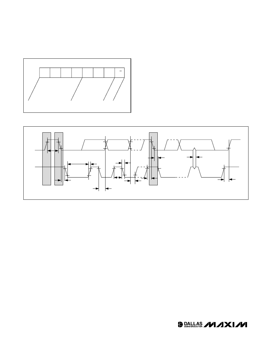
SDA
SCL
t
HD:STA
t
LOW
t
HIGH
t
R
t
F
t
BUF
t
HD:DAT
t
SU:DAT
REPEATED
START
t
SU:STA
t
HD:STA
t
SU:STO
t
SP
STOP
START
Figure 6. 2-Wire AC Characteristics
MSB
DEVICE
IDENTIFIER
DEVICE
ADDRESS
READ/WRITE BIT
1
0
1
1
A2
A1
A0
R/W
LSB
Figure 5. Slave Address