Rainbow Electronics DS1616 User Manual
Page 5
DS1616
5 of 28
MEMORY
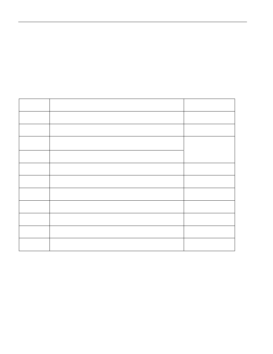
The memory map in Figure 2a shows the general organization of the DS1616. As can be seen in the
figure, the device is segmented into 32-byte pages. Pages 0 and 1 contain the RTC and Control registers
(see Figure 2b for more detail). The User NV RAM resides in page 2. Pages 17 to 19 are assigned to
storing the alarm time stamps and durations and pages 64 to 71 are reserved for histogram memory. The
data logging memory covers pages 128 to 191. Memory pages 3 to 16, 20 to 63, 68 to 127, and 192 and
up are reserved for future extensions.
The end user can write only to the RTC and Control registers and the User NV RAM. The rest of the
memory map is read-only from the end user’s perspective.
DS1616 MEMORY MAP Figure 2a
Address
Register definition
Page(s)
0000H
003FH
RTC and Control Registers
0 - 1
0040H
005FH
User NV RAM
2
0060H
0217H
(Reserved for Future Extensions)
3 – 16*
0218H
021FH
Serial Number
16**
0220H
027FH
Alarm Time Stamps and Durations
17 – 19
0280H
07FFH
(Reserved for Future Extensions)
20 – 63
0800H
087FH
Temperature Histogram (63 Bins of 2 Bytes Each)
64 – 67
0880H
08FFH
ADC Channel 1 Data Histogram (64 Bins of 2 Bytes Each)
68 – 71
0900H
0FFFH
(Reserved for Future Extensions)
72 – 127
1000H
17FFH
Datalog Memory (64 pages)
128 – 191
1800H
and higher
(Reserved for Future Extensions)
192 +
*
First 8 bytes
**
Last 8 bytes