Rainbow Electronics DS2712 User Manual
Page 8
DS2711/DS2712: Loose Cell NiMH Charger
8 of 13
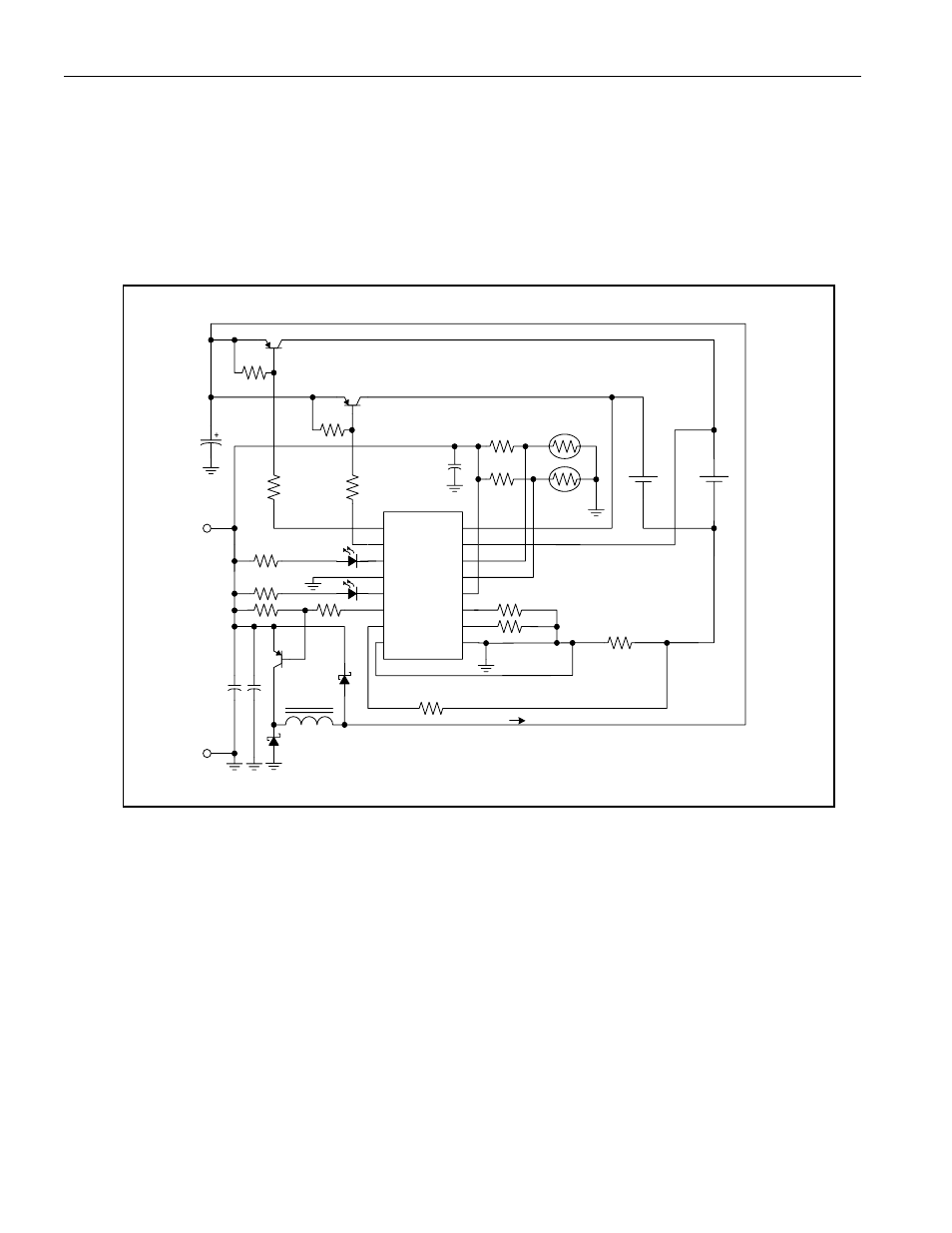
DS2712 Parallel Charge Configuration with Switch-Mode Charge Current Regulation
The example in Figure 5 uses the DS2712 to regulate charge current as a switching (buck) regulator. ICHG is set
to 2A using RSNS = 0.056
W. The effective charge current for each cell is ICHG x 0.484 = 968mA. The CSOUT
comparator output switches OFF when the voltage across the sense resistor goes above 0.125V and back ON
when the voltage drops below 0.100V. In this mode, the operating frequency is determined primarily by the value of
the hold-up capacitor (C1 in the diagram), the hysteresis, and the current drain. In some cases, a damping network
may be required to prevent overshoot with the batteries removed.
Figure 5. PARALLEL CONFIGURATION WITH SWITCH-MODE CURRENT
REGULATION (DS2712 ONLY)
CC1
CC2
LED1
VSS
LED2
CSOUT
VN1
VN0
VP1
VP2
THM2
THM1
VDD
CTST
0.056
270
1u
+5V
680
10K
270
DMSEL
TMR
10K
47u
10k
10k
75k
100k
10
47uHy
103AT-2
C1 47uF
DS2712
103AT-2
ICHG
0.1
GND
RSNS
FCX718
FCX718
100
100
150
FCX718