Table 4. parallel configuration, each cell, Table 5. series configuration, each cell – Rainbow Electronics DS2712 User Manual
Page 13
DS2711/DS2712: Loose Cell NiMH Charger
13 of 13
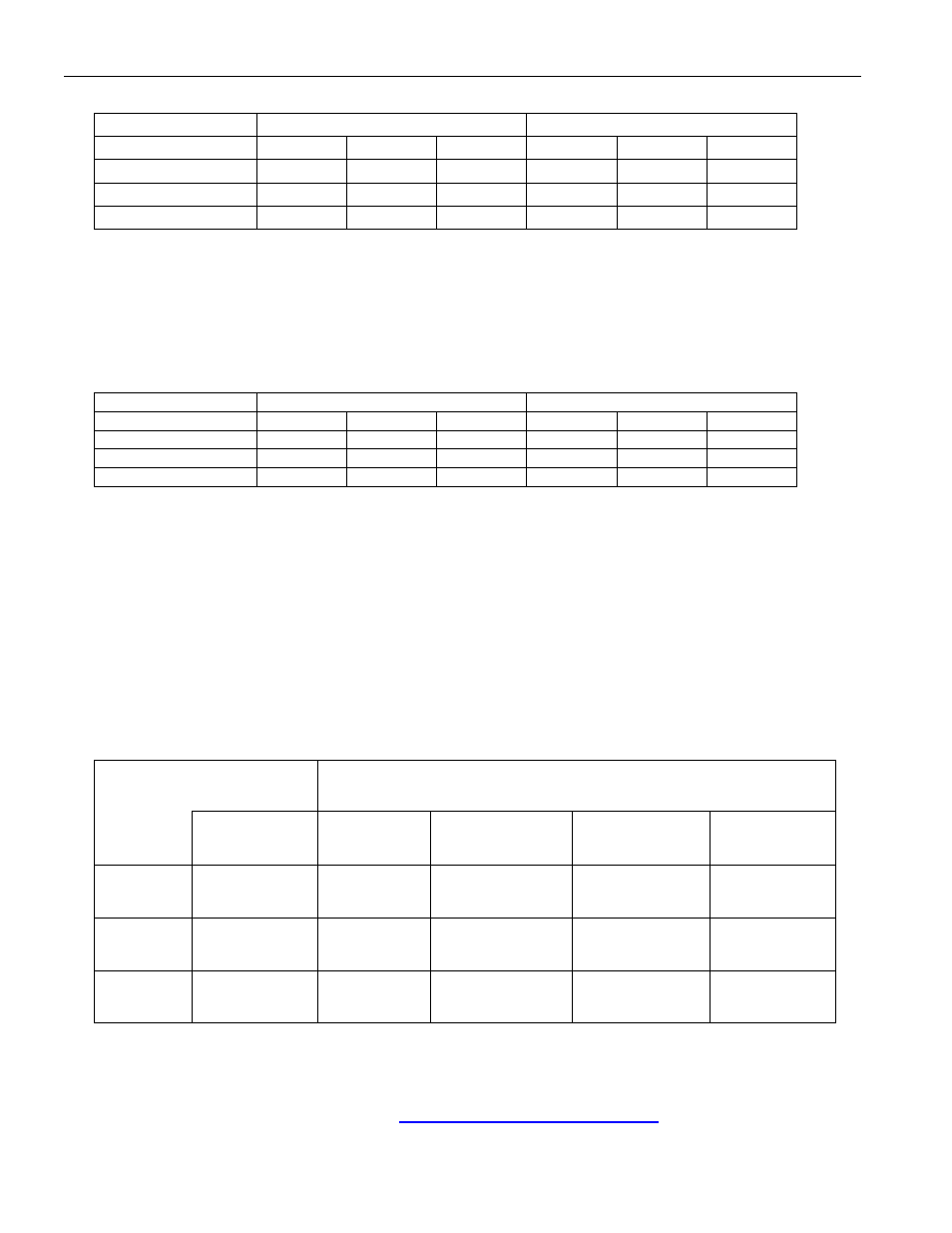
Table 4. PARALLEL CONFIGURATION, EACH CELL
MODE
CURRENT LIMIT 500mA
CURRENT LIMIT 1000mA
Cell
Capacity
900mAH 1700mAH 2200mAH 900mAH 1700mAH 2200mAH
Fast
C/3.72 C/7.02 C/9.08 C/1.86 C/3.51 C/4.54
Precharge/Top-Off
C/14.4 C/27.2 C/35.2 C/7.20 C/13.6 C/17.6
Maintenance
C/115 C/218 C/282 C/57.6 C/109 C/141
Series and Single Cell Charging Example:
In the series and single-cell modes, the effective fast charge current is equal to 0.969 times the regulated current
limit and the top-off current is 0.25 times the regulated current. The maintenance mode is identical to the parallel
charging rate, that is, 1/64 times the regulated current. The C-rates for charging 3 different cell capacities using a
500mA and a 1000mA current source are shown in the following table.
Table 5. SERIES CONFIGURATION, EACH CELL
MODE
CURRENT LIMIT 500mA
CURRENT LIMIT 1000mA
Cell
Capacity
900mAH 1700mAH 2200mAH 900mAH 1700mAH 2200mAH
Fast
C/1.86 C/3.51 C/4.54 C/0.93 C/1.75 C/2.27
Precharge/Top-Off
C/7.20 C/13.6 C/17.6 C/3.60 C/6.80 C/8.80
Maintenance
C/115 C/218 C/282 C/57.6 C/109 C/141
LED1 and LED2 Outputs, MODE-Select Input
Open-drain outputs LED1 and LED2 pull low to indicate charge status. When inactive, the outputs are high
impedance. LED1 displays the status for the cell monitored by VP1 and LED2 displays the status for the cell
monitored by VP2.
The LED pins drive low in three “blink” patterns to annunciate the charge status. Table 6 summarizes the LED
operation in each display mode (DM0, DM1, DM2) for each charge condition. In parallel mode, LED1 indicates the
status of the cell whose positive terminal is connected to VP1 and LED2 indicates the status of the cell whose
positive terminal is connected to VP2. In series mode, LED1 indicates the charge status for both cells since they
are charged in series.
Table 6. DISPLAY PATTERNS BY DISPLAY MODE AND CHARGE ACTIVITY
DISPLAY MODE
CHARGE ACTIVITY
DMSEL
PIN
NO
BATTERY
PRE/FAST/TOP-
OFF
CHARGING
MAINTENANCE FAULT
DM0
Low High-Z Low
0.80s Low
0.16s High-Z
0.48s Low
0.48s High-Z
DM1
Float High-Z Low
High-Z
0.16s Low
0.16s High-Z
DM2
High High-Z
0.80s Low
0.16s High-Z
Low
0.16s Low
0.16s High-Z
High-Z = High Impedance
Package Information
For the latest package outline information, go to
www.maxim-ic.com/DallasPackInfo
.