Parallel charge configuration – Rainbow Electronics DS2712 User Manual
Page 7
DS2711/DS2712: Loose Cell NiMH Charger
7 of 13
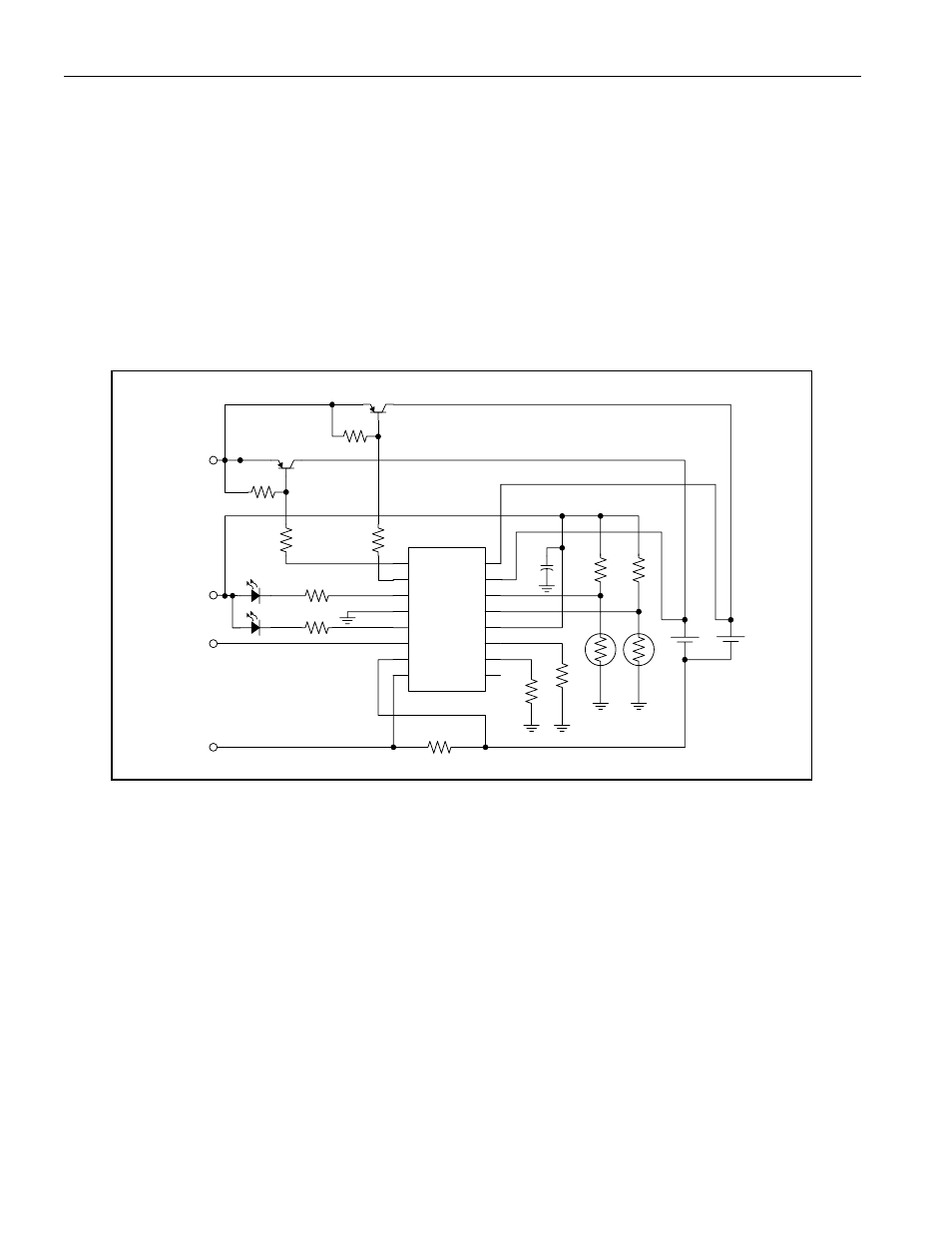
Parallel Charge Configuration
The parallel configuration supports two slot stand-alone chargers. Charge pulses are fed alternately to each cell
under the control of the CC1 and CC2 pins so the charge regimes occur in parallel. The duty cycle on CC1 and
CC2 are independent of one another. Transitions from precharge to fast charge, fast charge to top-off, and top-off
to maintenance occur independently for each cell.
The configuration shown in Figure 4 is for charging two cells with the current-sense feedback regulating the charge
source to 2A (RSNS = 0.068
W). The effective charge current for each cell is 2A x 0.484 = 0.968A. A charger with
battery holders designed to accept either AA or AAA cell sizes can be constructed with the current-sense
resistance split between two separate resistors so each cell type (AA or AAA) is charged at a different rate.
Mechanical design of the holders is required to prevent insertion of more than one cell in each slot. The holder
design must also prevent electrical contact with reverse polarity insertion.
Figure 4. PARALLEL CONFIGURATION WITH EXTERNAL CURRENT
REGULATION
VDD
LED1
LED2
DMSEL
CTST
TMR
CSOUT
VP1
VP2
THM1
THM2
VN1
VSS
VN0
CC1
CC2
75K
100K
10K
x2
103AT-2
x2
DS2711/12
270
0.068
10K
FCX718
+5V
GND
IFB
ICHG
100
10K
FCX718
270
RSNS
100
0.1
The series or parallel charge configuration is programmed by strapping LED2 in the low, high, or high-Z (float) state
during power-up. In this example and the following one, the parallel charge mode is selected by pulling LED2 pin
high during power-up. This is accomplished in this example by the LED and 270
W resistor. In applications where
only one LED is used, a 100k
W pullup resistor is recommended. See Table 3. CHARGE MODE SELECTION on
page 12 for additional configuration programming information.